| PINPOINT TEST A : ELECTRIC ENGINE COOLANT HEATER INOPERATIVE / PARTLY INOPERATIVE |
| TEST CONDITIONS | DETAILS/RESULTS/ACTIONS |
| A1: CHECK THE ELECTRIC ENGINE COOLANT HEATER |
NOTE:The electric engine coolant heater only works when the ambient temperature is below 5°C, the coolant temperature does not exceed 71°C and sufficient generator capacity is available. |
| | 1 Allow the engine to run. |
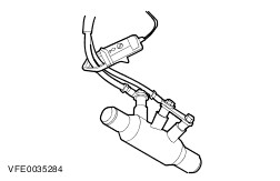
| | 2 Measure the current in circuits 15S-RH24 (GN/OG), 15S-RH26A (GN/WH) and 15S-RH26B (GN/WH) at the electric engine coolant heater using the clip-on ammeter. |
| | Is a current measured? Yes No |
| A2: CHECK 1ST STAGE OF ELECTRIC ENGINE COOLANT HEATER CIRCUIT |
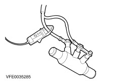
| | 1 Measure the current in circuit 15S-RH24 (GN/OG) at the electric engine coolant heater using the clip-on ammeter. |
| | Is a current of more than 10 A measured? Yes No |
| A3: CHECK FUSE F3 |
| | 1 Ignition switch in position 0. |
| | 2 CHECK fuse F3 (BJB). |
| | Is the fuse OK? Yes No RENEW fuse F3 (60 A). If the fuse blows again, LOCATE and REPAIR the short to ground using the Wiring Diagrams. CHECK the operation of the system. |
| A4: CHECK THE VOLTAGE AT FUSE F3 |
| | 1 Connect fuse F3 (BJB). |
| | 2 Measure the voltage between fuse F3 (60 A) and ground. |
| | Does the meter display battery voltage? Yes No REPAIR the voltage supply to fuse F3 using the Wiring Diagrams. CHECK the operation of the system. |
| A5: CHECK FUSE F82 |
| | 1 CHECK fuse F82 (CJB). |
| | Is the fuse OK? Yes No RENEW fuse F82 (7.5 A). If the fuse blows again, LOCATE and REPAIR the short to ground using the Wiring Diagrams. CHECK the operation of the system. |
| A6: CHECK THE VOLTAGE AT FUSE F82 |
| | 1 Connect fuse F82 (CJB). |
| | 2 Ignition switch in position II. |
| | 3 Measure the voltage between fuse F82 (7.5 A) and ground. |
| | Does the meter display battery voltage? Yes No REPAIR the voltage supply to fuse F82 using the Wiring Diagrams. CHECK the operation of the system. |
| A7: CHECK VOLTAGE AT RELAY 1, ELECTRIC ENGINE COOLANT HEATER |
| | 1 Ignition switch in position 0. |
| | 2 Disconnect relay 1, electric engine coolant heater from socket C125. |
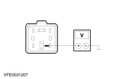
| | 3 Measure the voltage between relay 1, electric engine coolant heater, connector C125, pin 3, circuit 30-RH24A (RD), wiring harness side and ground. |
| | Does the meter display battery voltage? Yes No LOCATE and REPAIR the break in the circuit between fuse F3 and soldered connection S361 using the Wiring Diagrams. CHECK the operation of the system. |
| A8: CHECK CONTROL VOLTAGE AT RELAY 1, ELECTRIC ENGINE COOLANT HEATER |
| | 1 Ignition switch in position II. |
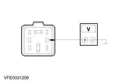
| | 2 Measure the voltage between relay 1, electric engine coolant heater, connector C125, pin 1, circuit 15-RH23 (GN/RD), wiring harness side and ground. |
| | Does the meter display battery voltage? Yes No LOCATE and REPAIR break in circuit between relay 1, electric engine coolant heater or relay 2, electric engine coolant heater and fuse F82 using the Wiring Diagrams. CHECK the operation of the system. |
| A9: CHECK THE GROUND CONNECTION OF THE ENGINE COOLANT HEATER |
| | 1 Ignition switch in position 0. |
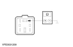
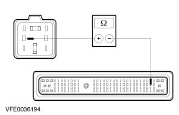
| | 2 Measure the resistance between relay 1, electric engine coolant heater, connector C125, pin 5, circuit 15S-RH24 (GN/OG) and ground. |
| | Is a resistance of less than 1.2 Ohm registered? Yes No |
| A10: CHECK THE ELECTRIC ENGINE COOLANT HEATER GLOW PLUG |
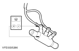
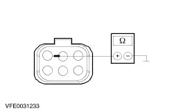
| | 1 Measure the resistance between electric engine coolant heater, connector C123, pin 1, circuit 15S-RH24 (GN/OG), component side and electric engine coolant heater housing. |
| | Is a resistance of less than 1.2 Ohm registered? Yes CHECK the ground connection of the electric engine coolant heater, if necessary CLEAN the threaded connection(s) on the bulkhead. CHECK the operation of the system. No RENEW the electric engine coolant heater. CHECK the operation of the system. |
| A11: CHECK THE SIGNAL FROM THE INTAKE AIR TEMPERATURE SENSOR |
NOTE:The intake air temperature sensor is integrated in the mass air flow sensor (MAF, engine management). |
| | 1 Connect the diagnostic tool. |
| | 2 Check the intake air temperature signal using the diagnostic unit. |
| | Is the intake air temperature signal OK, i.e. is the indicated temperature value plausible? Yes Check the powertrain control module (PCM) and RENEW as necessary. CHECK the operation of the system. No |
| A12: CHECK VOLTAGE AT RELAY 1, ELECTRIC ENGINE COOLANT HEATER |
| | 1 Ignition switch in position 0. |
| | 2 Disconnect relay 1, electric engine coolant heater from socket C125. |
| | 3 Measure the voltage between relay 1, electric engine coolant heater, connector C125, pin 3, circuit 30-RH24A (RD), wiring harness side and ground. |
| | Does the meter display battery voltage? Yes No LOCATE and RECTIFY the break in circuit 30-RH24A (RD) between relay 1, electric engine coolant heater and solder point S361 using the Wiring Diagrams. CHECK the operation of the system. |
| A13: CHECK CONTROL VOLTAGE AT RELAY 1, ELECTRIC ENGINE COOLANT HEATER |
| | 1 Ignition switch in position II. |
| | 2 Measure the voltage between relay 1, electric engine coolant heater, connector C125, pin 1, circuit 15-RH23 (GN/RD), wiring harness side and ground. |
| | Does the meter display battery voltage? Yes No LOCATE and RECTIFY the break in circuit 15-RH23 (GN/RD) between relay 1, electric engine coolant heater and fuse F82 using the Wiring Diagrams. CHECK the operation of the system. |
| A14: CHECK THE CIRCUIT BETWEEN RELAY 1, ELECTRIC ENGINE COOLANT HEATER AND THE ELECTRIC ENGINE COOLANT HEATER FOR OPEN CIRCUIT. |
| | 1 Ignition switch in position 0. |
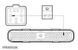
| | 2 Measure the resistance between relay 1, electric engine coolant heater, socket C125, pin 5, circuit 15S-RH24 (GN/OG), wiring harness side and ground. |
| | Is a resistance of less than 1.2 Ohm registered? Yes No |
| A15: CHECK THE ELECTRIC ENGINE COOLANT HEATER |
| | 1 Disconnect connector C124. |
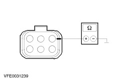
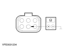
| | 2 Measure the resistance between connector C124, pin 1, circuit 15S-RH24 (GN/OG), component side and ground. |
| | Is a resistance of less than 1.2 Ohm registered? Yes LOCATE and RECTIFY the break in circuit 15S-RH24 (GN/OG) between relay 1, electric engine coolant heater and the electric engine coolant heater using the Wiring Diagrams. CHECK the operation of the system. No RENEW the electric engine coolant heater. CHECK the operation of the system. |
| A16: CHECK RELAY 1, ELECTRIC ENGINE COOLANT HEATER |
| | 1 Check relay 1, electric engine coolant heater in accordance with the component test at the end of this section. |
| | Is relay 1, electric engine coolant heater OK? Yes - All except vehicles with common rail injection system and integrated injector module (IDM): GO to A17. - Vehicles with common rail injection system and integrated IDM: GO to A18. No RENEW relay 1, electric engine coolant heater. CHECK the operation of the system. |
| A17: CHECK FOR BREAK IN CIRCUIT BETWEEN THE PCM AND RELAY 1, ELECTRIC ENGINE COOLANT HEATER - ALL EXCEPT VEHICLES WITH COMMON RAIL INJECTION SYSTEM AND INTEGRATED IDM |
| | 1 Disconnect connector C100 from PCM. |
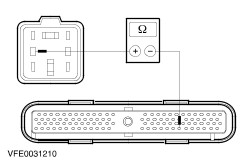
| | 2 Measure resistance between relay 1, electric engine coolant heater, socket C125, pin 2, circuit 91S-RH23 (BK/OG), wiring harness side and PCM, connector C100, pin 98, circuit 91S-RH23 (BK/OG), wiring harness side. |
| | Is a resistance of less than 2 Ohm registered? Yes CHECK the PCM and RENEW if necessary. CHECK the operation of the system. No LOCATE and RECTIFY the break in circuit 91S-RH23 (BK/OG) between PCM and relay 1, electric engine coolant heater using the Wiring Diagrams. CHECK the operation of the system. |
| A18: CHECK FOR BREAK IN CIRCUIT BETWEEN THE PCM AND RELAY 1, ELECTRIC ENGINE COOLANT HEATER - VEHICLES WITH COMMON RAIL INJECTION SYSTEM AND INTEGRATED IDM |
| | 1 Disconnect connector C200 from PCM. |
| | 2 Measure resistance between relay 1, electric engine coolant heater, socket C125, pin 2, circuit 91S-RH23 (BK/OG), wiring harness side and PCM, connector C200, pin 61, circuit 91S-RH23 (BK/OG), wiring harness side. |
| | Is a resistance of less than 2 Ohm registered? Yes CHECK the PCM and RENEW if necessary. CHECK the operation of the system. No LOCATE and RECTIFY the break in circuit 91S-RH23 (BK/OG) between PCM and relay 1, electric engine coolant heater using the Wiring Diagrams. CHECK the operation of the system. |
| A19: CHECK VOLTAGE AT RELAY 2, ELECTRIC ENGINE COOLANT HEATER |
| | 1 Ignition switch in position 0. |
| | 2 Disconnect relay 2, electric engine coolant heater from socket C126. |
| | 3 Measure the voltage between relay 2, electric engine coolant heater, connector C126, pin 3, circuit 30-RH26 (RD), wiring harness side and ground. |
| | Does the meter display battery voltage? Yes No LOCATE and RECTIFY the break in circuit 30-RH26 (RD) between relay 2, electric engine coolant heater and solder point S361 using the Wiring Diagrams. CHECK the operation of the system. |
| A20: CHECK CONTROL VOLTAGE AT RELAY 2, ELECTRIC ENGINE COOLANT HEATER |
| | 1 Ignition switch in position II. |
| | 2 Measure the voltage between relay 2, electric engine coolant heater, connector C126, pin 1, circuit 15-RH25 (GN/BK), wiring harness side and ground. |
| | Does the meter display battery voltage? Yes No LOCATE and RECTIFY the break in circuit 15-RH25 (GN/BK) between relay 2, electric engine coolant heater and fuse F82 using the Wiring Diagrams. CHECK the operation of the system. |
| A21: CHECK THE CIRCUIT BETWEEN RELAY 2, ELECTRIC ENGINE COOLANT HEATER AND THE ELECTRIC ENGINE COOLANT HEATER FOR OPEN CIRCUIT. |
| | 1 Ignition switch in position 0. |
| | 2 Measure the resistance between relay 2, electric engine coolant heater, connector C126, pin 5, circuit 15S-RH26 (GN/WH), wiring harness side and ground. |
| | Is a resistance of less than 0.7 Ohm registered? Yes No |
| A22: CHECK THE ELECTRIC ENGINE COOLANT HEATER |
| | 1 Disconnect connector C124. |
| | 2 Measure the resistance between connector C124, pin 3, circuit 15S-RH26B (GN/WH), component side and ground. |
| | Is a resistance of less than 1.2 Ohm registered? Yes No RENEW the electric engine coolant heater. CHECK the operation of the system. |
| A23: CHECK THE ELECTRIC ENGINE COOLANT HEATER |
| | 1 Measure the resistance between connector C124, pin 5, circuit 15S-RH26A (GN/WH), component side and ground. |
| | Is a resistance of less than 1.2 Ohm registered? Yes LOCATE and RECTIFY the break in circuit 15S-RH26 (GN/WH), 15S-RH26A (GN/WH) or 15S-RH26B (GN/WH) between relay 2, electric engine coolant heater and the electric engine coolant heater using the Wiring Diagrams. CHECK the operation of the system. No RENEW the electric engine coolant heater. CHECK the operation of the system. |
| A24: CHECK RELAY 2, ELECTRIC ENGINE COOLANT HEATER |
| | 1 Check relay 2, electric engine coolant heater in accordance with the component test at the end of this section. |
| | Is relay 2, electric engine coolant heater OK? Yes - All except vehicles with common rail injection system and integrated injector module (IDM): GO to A25. - Vehicles with common rail injection system and integrated IDM: GO to A26. No RENEW relay 2, electric engine coolant heater. CHECK the operation of the system. |
| A25: CHECK FOR BREAK IN CIRCUIT BETWEEN THE PCM AND RELAY 2, ELECTRIC ENGINE COOLANT HEATER - ALL EXCEPT VEHICLES WITH COMMON RAIL INJECTION SYSTEM AND INTEGRATED IDM |
| | 1 Disconnect connector C100 from PCM. |
| | 2 Measure resistance between relay 2, electric engine coolant heater, socket C126, pin 2, circuit 91S-RH25 (BK/GN), wiring harness side and PCM, connector C100, pin 75, circuit 91S-RH25 (BK/GN), wiring harness side. |
| | Is a resistance of less than 2 Ohm registered? Yes CHECK the PCM and RENEW if necessary. CHECK the operation of the system. No LOCATE and RECTIFY the break in circuit 91S-RH25 (BK/GN) between PCM and relay 2, electric engine coolant heater using the Wiring Diagrams. CHECK the operation of the system. |
| A26: CHECK FOR BREAK IN CIRCUIT BETWEEN THE PCM AND RELAY 2, ELECTRIC ENGINE COOLANT HEATER - VEHICLES WITH COMMON RAIL INJECTION SYSTEM AND INTEGRATED IDM |
| | 1 Disconnect connector C200 from PCM. |
| | 2 Measure resistance between relay 2, electric engine coolant heater, socket C126, pin 2, circuit 91S-RH25 (BK/GN), wiring harness side and PCM, connector C200, pin 62, circuit 91S-RH25 (BK/GN), wiring harness side. |
| | Is a resistance of less than 2 Ohm registered? Yes CHECK the PCM and RENEW if necessary. CHECK the operation of the system. No LOCATE and RECTIFY the break in circuit 91S-RH25 (BK/GN) between PCM and relay 2, electric engine coolant heater using the Wiring Diagrams. CHECK the operation of the system. |