| Diagnosis and Testing Refer to Wiring Diagrams Section 413-06, for schematic and connector information. Inspection and Verification - Verify the customer concern.
- Visually inspect for obvious signs of electrical damage.
Visual Inspection Chart | Electrical | - Fuse(s)
- Wiring harness
- Electrical connector(s)
- Clock
| - If an obvious cause for an observed or reported concern is found, correct the cause (if possible) before proceeding to the next step.
- If the cause is not visually evident, verify the symptom and refer to the Symptom Chart.
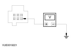
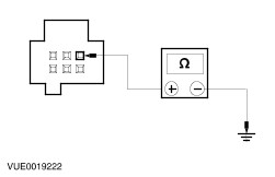
Symptom Chart Symptom Chart | Symptom | Possible Sources | Action | | The clock operation is erratic/inoperative | * Fuse(s). * Circuit. * Clock. | * GO to Pinpoint Test ??. | Pinpoint Tests NOTE:Use a digital multimeter for all electrical measurements | PINPOINT TEST A : THE CLOCK OPERATION IS ERRATIC/INOPERATIVE | | TEST CONDITIONS | DETAILS/RESULTS/ACTIONS | | A1: CHECK CIRCUIT 29-GB6 (OG/YE) FOR VOLTAGE | | | 1 Ignition switch in position 0. | | | 2 Disconnect Clock C412. | | | 3 Measure the voltage between clock C412 pin 6, circuit 29-GB6 (OG/YE), harness side and ground. | | | Is the voltage greater than 10 volts? Yes No CHECK fuse F75 (7.5A). INSTALL a new fuse as required. If the fuse fails again check for short to ground. REPAIR the circuit. TEST the system for normal operation. | | A2: CHECK CIRCUIT 31-GB6 (BK) FOR OPEN | | | 1 Measure the resistance between C412 pin 3, circuit 31-GB6 (BK), harness side and ground. | | | Is the resistance less than 5 ohms? Yes INSTALL a new clock. REFER to Clock in this section. TEST the system for normal operation. No REPAIR the circuit. TEST the system for normal operation. | |