| Diagnosis and Testing Refer to Wiring Diagrams Section 413-09, for schematic and connector information. Principles of Operation Belt Minder The belt minder feature is a supplemental warning that augments the current safety belt warning function. This feature continually reminds the driver that their safety belt is unbuckled by intermittently sounding a chime and illuminating the safety belt warning indicator in the instrument cluster once the vehicle speed has exceeded 5 mph (7 km/h). Immediately after ignition is turned to position II the belt minder is activated. The belt minder alternates from ON for six seconds and OFF for 30 seconds until deactivated. The belt minder will be deactivated under the following conditions: - ignition switch is turned to position 0.
- ignition switch is turned to position I.
- five minutes has elapsed with the belt minder activated.
If the customer buckles their safety belt prior to the belt minder becoming active, the belt minder will remain inactive, Therefore will not provide a reminder, until the correct conditions are met as described above on the NEXT ignition cycle from OFF or position I to position II. Inspection and Verification - Verify the customer concern.
- Visually inspect for obvious signs of mechanical or electrical damage.
Visual Inspection Chart | Mechanical | Electrical | | | - Fuse(s)
- Wiring harness(es)
- Electrical connector(s)
- Switch(es)
- Sensor(s)
- Generic electronic module (GEM)
| - If an obvious cause for an observed or reported concern is found, correct the cause (if possible) before proceeding to the next step.
- Insert an ignition key into the ignition lock cylinder and turn the ignition key from position 0, to position II.
- Is the air bag warning indicator illuminated?
- If yes,
REFER to: Air Bag and Safety Belt Pretensioner Supplemental Restraint System (SRS) (501-20B Supplemental Restraint System, Diagnosis and Testing).
- If no, CARRY OUT the safety belt minder activating procedure.
REFER to: Safety Belt Minder Deactivating/Activating (413-09 Warning Devices, General Procedures).
- Is the safety belt warning indicator flashing (3 flashes within 3 seconds) ?
- If yes, TEST the system for normal operation.
- If no, continue with the diagnostic procedure.
- If no, continue with the diagnostic procedure verify the symptom and refer to the Symptom Chart.
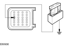
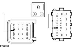
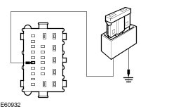
Symptom Chart Symptom Chart | Symptom | Possible Sources | Action | | The safety belt indicator does not illuminate, for vehicles built from 02/2002 to 08/2002 and for vehicles built from 06/2003 to 06/2004. | * Circuit(s). * Generic electronic module (GEM) * Restraints control module (RCM) * Instrument cluster | * | | The safety belt indicator does not illuminate, for vehicles built from 08/2002 to 06/2003. | * Circuit(s). * GEM * Instrument cluster * Belt minder module | * | | The safety belt indicator does not illuminate, for vehicles built from 06/2004. | * Circuit(s) * GEM * Instrument cluster | * | Pinpoint Tests | PINPOINT TEST A : THE SAFETY BELT INDICATOR DOES NOT ILLUMINATE, FOR VEHICLES BUILT FROM 02/2002 TO 08/2002 AND FOR VEHICLES BUILT FROM 06/2003 TO 06/2004. | | TEST CONDITIONS | DETAILS/RESULTS/ACTIONS | | A1: CHECK SEAT BELT INDICATOR FOR CORRECT OPERATION | | | 1 Disconnect RCM C490. | | | 2 Install a fused (7.5A) jumper wire between the RCM C490 pin 22, circuit 91S-GE49 (BK/BU), harness side and ground. | | | 3 Ignition switch in position II. | | | Is the safety belt warning indicator illuminated? Yes INSTALL a new RCM. TEST the system for normal operation. No | | A2: CHECK CIRCUIT 91S-GE49A (BK/BU) FOR OPEN | | | 1 Ignition switch in position 0. | | | 2 Disconnect GEM C427. | | | 3 Measure the resistance between the RCM C490, pin 22 circuit 91S-GE49A (BK/BU), harness side and the GEM C427 pin 17, circuit 91S-GE49A (BK/BU), harness side. | | | Is the resistance less than 5 ohms? Yes No REPAIR the circuit. TEST the system for normal operation. | | A3: CHECK SEAT BELT INDICATOR FOR CORRECT OPERATION | | | 1 Disconnect GEM 430. | | | 2 Install a fused (7.5A) jumper wire between the GEM C430 pin 18, circuit 91S-GE49A (BK/BU), harness side and ground. | | | 3 Ignition switch in position II. | | | Is the safety belt warning indicator illuminated? Yes INSTALL a new GEM.
REFER to: Generic Electronic Module (GEM) (419-10 Multifunction Electronic Modules, Removal and Installation).
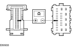
TEST the system for normal operation. No | | A4: CHECK CIRCUIT 91S-GE49A (BK/BU) FOR OPEN | | | 1 Disconnect Instrument Cluster C449. | | | 2 Measure the resistance between the instrument cluster C449 pin 26, circuit 91S-GE49A (BK/BU), harness side and the GEM C430, pin 18, circuit 91S-GE49A (BK/BU), harness side. | | | Is the resistance less than 5 ohms? Yes INSTALL a new instrument cluster.
REFER to: Instrument Cluster (413-01 Instrument Cluster, Removal and Installation).
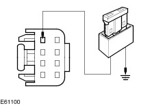
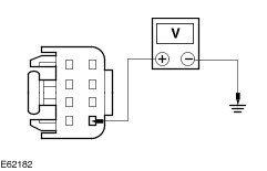
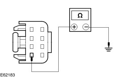
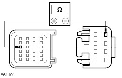
Test the system for normal operation. No REPAIR the circuit. TEST the system for normal operation. | | PINPOINT TEST B : THE SAFETY BELT INDICATOR DOES NOT ILLUMINATE, FOR VEHICLES BUILT FROM 08/2002 TO 06/2003. | | TEST CONDITIONS | DETAILS/RESULTS/ACTIONS | | B1: CHECK SAFETY BELT INDICATOR FOR CORRECT OPERATION | | | 1 Disconnect RCM C490. | | | 2 Install a fused (7.5A) jumper wire between the RCM C490 pin 22, circuit 91S-GE49 (BK/BU), harness side and ground. | | | 3 Ignition switch in position II. | | | Is the safety belt warning indicator illuminated? Yes INSTALL a new RCM. TEST the system for normal operation. No | | B2: CHECK SAFETY BELT INDICATOR FOR CORRECT OPERATION | | | 1 Disconnect Belt Minder Module C1016. | | | 2 Install a fused (7.5A) jumper wire between the belt minder module C1016 pin 4, circuit 91S-GE49 (BK/BU), harness side and ground. | | | 3 Ignition switch in position II. | | | Is the safety belt warning indicator illuminated? Yes No | | B3: CHECK THE BELT MINDER MODULE FOR POWER | | | 1 Ignition switch in position II. | | | 2 Measure the voltage between the belt minder module C1016 pin 5, circuit 15-JA52, pin 5 (GN/BK), harness side and ground. | | | Is the voltage greater than 10 volts? Yes No REPAIR the circuit. TEST the system for normal operation | | B4: CHECK THE BELT MINDER MODULE FOR GROUND | | | 1 Ignition switch in position 0. | | | 2 Measure the resistance between the belt minder module C1016 pin 1, circuit 91-JA52 (BK/GN), harness side and ground. | | | Is the resistance less than 5 ohms? Yes INSTALL a new belt minder module. Test the system for normal operation. No REPAIR the circuit. TEST the system for normal operation. | | B5: CHECK CIRCUIT 91S-GE49A (BK/BU) FOR OPEN | | | 1 Ignition switch in position 0. | | | 2 Disconnect GEM C427. | | | 3 Measure the resistance between the RCM C490 pin 22, circuit 91S-GE49A (BK/BU), harness side and the belt minder module C1016 pin 8, circuit 91S-GE49A (BK/BU), harness side. | | | Is the resistance less than 5 ohms? Yes No REPAIR the circuit. TEST the system for normal operation. | | B6: CHECK SAFETY BELT INDICATOR FOR CORRECT OPERATION | | | 1 Disconnect GEM 430. | | | 2 Install a fused (7.5A) jumper wire between the GEM C430 pin 18, circuit 91S-GE49A (BK/BU), harness side and ground. | | | 3 Ignition switch in position II. | | | Is the safety belt warning indicator illuminated? Yes INSTALL a new GEM.
REFER to: Generic Electronic Module (GEM) (419-10 Multifunction Electronic Modules, Removal and Installation).
TEST the system for normal operation. No | | B7: CHECK CIRCUIT 91S-GE49A (BK/BU) FOR OPEN | | | 1 Disconnect Instrument Cluster C449. | | | 2 Measure the resistance between the instrument cluster C449 pin 26, circuit 91S-GE49A (BK/BU), harness side and the GEM C430 pin 18, circuit 91S-GE49A (BK/BU), harness side. | | | Is the resistance less than 5 ohms? Yes INSTALL a new instrument cluster.
REFER to: Instrument Cluster (413-01 Instrument Cluster, Removal and Installation).
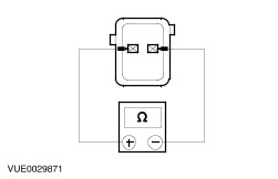
Test the system for normal operation. No REPAIR the circuit. TEST the system for normal operation. | | PINPOINT TEST C : THE SAFETY BELT INDICATOR DOES NOT ILLUMINATE, FOR VEHICLES BUILT FROM 06/2004. | | TEST CONDITIONS | DETAILS/RESULTS/ACTIONS | | C1: CHECK THE DRIVERS SIDE SAFETY BELT BUCKLE SWITCH FOR CORRECT OPERATION | WARNING:Wait at least one minute after disconnecting the battery ground cable before disconnecting any supplemental restraint system electrical connector. Failure to follow this instruction may result in personal injury. | | | 1 Ignition switch in position 0. | | | 2 Disconnect Safety Belt Buckle Switch C60f. | | | 3 Measure the resistance between the safety belt buckle switch C60f, pin 1 and pin 2, component side. | | | 4 Connect the safety belt buckle in to the seat belt pretensioner. | | | 5 Measure the resistance between the safety belt buckle switch C60f pin 1 and pin 2, component side. | | | Does the resistance change from less than 5 ohms to more than 10,000 ohms when the safety belt is connected? Yes No INSTALL a new safety belt buckle and pretensioner.
REFER to: Safety Belt Buckle and Pretensioner (501-20A Safety Belt System, Removal and Installation).
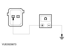
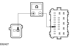
TEST the system for normal operation. | | C2: CHECK CIRCUIT 91-GE52A (BK/RD) FOR GROUND | WARNING:Wait at least one minute after disconnecting the battery ground cable before disconnecting any supplemental restraint system electrical connector. Failure to follow this instruction may result in personal injury. | | | 1 Measure the resistance between the safety belt buckle switch C60F, pin 1, circuit 91-GE52A (BK/RD), harness side and ground. | | | Is the resistance less than 5 ohms? Yes No REPAIR the circuit. TEST the system for normal operation. | | C3: CHECK CIRCUIT 91S-GE49A (BK/BU) FOR OPEN | | | 1 Disconnect GEM 427. | | | 2 Measure the resistance between the safety belt buckle switch C60F, pin 2, circuit 91S-GE49A (BK/BU), harness side and the GEM C427 pin 17, circuit 91S-GE49A (BK/BU), harness side. | | | Is the resistance less than 5 ohms? Yes No REPAIR the circuit. TEST the system for normal operation. | | C4: CHECK SAFETY BELT INDICATOR FOR CORRECT OPERATION | | | 1 Disconnect GEM 430. | | | 2 Install a fused (7.5A) jumper wire between the GEM C430 pin 18, circuit 91S-GE49A (BK/BU), harness side and ground. | | | 3 Ignition switch in position II. | | | Is the safety belt warning indicator illuminated? Yes INSTALL a new GEM.
REFER to: Generic Electronic Module (GEM) (419-10 Multifunction Electronic Modules, Removal and Installation).
TEST the system for normal operation. No | | C5: CHECK CIRCUIT 91S-GE49A (BK/BU) FOR OPEN | | | 1 Disconnect Instrument Cluster C449. | | | 2 Disconnect GEM 430. | | | 3 Measure the resistance between the instrument cluster C449 pin 26, circuit 91S-GE49A (BK/BU), harness side and the GEM C430, pin 18, circuit 91S-GE49A (BK/BU), harness side. | | | Is the resistance less than 5 ohms? Yes INSTALL a new instrument cluster.
REFER to: Instrument Cluster (413-01 Instrument Cluster, Removal and Installation).
Test the system for normal operation. No REPAIR the circuit. TEST the system for normal operation. | |