| PINPOINT TEST B : HEADLAMP LEVELLING SYSTEM IS INOPERATIVE, VEHICLES WITH GAS DISCHARGE LAMPS |
| TEST CONDITIONS | DETAILS/RESULTS/ACTIONS |
| B1: READ OUT THE FAULT MEMORY |
| | 1 Ignition switch in position 0. |
| | 2 Connect the diagnostic tool. |
| | 3 Check the system using WDS. |
| | Are any trouble codes (DTCs) displayed? Yes RESOLVE the faults according to the WDS instructions. CLEAR the fault memory and CHECK the operation of the system. No |
| B2: ESTABLISH FAULT CONDITION |
NOTE: On vehicles with gas discharge lamps the headlamp levelling takes place automatically according to the loading of the vehicle. The basic settings should be performed once on an unladen vehicle with the aid of WDS. |
| | 1 Ignition switch in position II. |
| | 2 Switch on the dipped beam. |
| | 3 Simulate an unladen vehicle. |
| | 4 Simulate a laden vehicle. |
| | 5 Check the operation of the headlamp levelling system. |
| | Is the headlamp levelling system inoperative on both sides? Yes No Headlamp levelling system inoperative on the left-hand side: GO to B3. Headlamp levelling system inoperative on the right-hand side: GO to B24. |
| B3: CHECK FUSE F93 (CJB) |
| | 1 Ignition switch in position 0. |
| | 2 Disconnect Fuse F93 (CJB) . |
| | 3 CHECK Fuse F93 (10 A) . |
| | Is the fuse OK.? Yes No INSTALL a new fuse F93 (10 A). If fuse blows again, LOCATE and REMEDY the short to ground with the aid of the wiring diagrams. CHECK the operation of the system. |
| B4: CHECK THE VOLTAGE AT FUSE F93 (CJB) |
| | 1 Connect Fuse F93 (CJB) . |
| | 2 Ignition switch in position II. |
| | 3 Switch on the dipped beam. |
| | 4 Measure the voltage between fuse F93 (CJB) and ground. |
| | Is battery voltage displayed? Yes No LOCATE AND RECTIFY the break in the voltage supply of fuse F93 (CJB) with the aid of the wiring diagrams, if necessary CHECK AND RENEW CJB. CHECK the operation of the system. |
| B5: CHECK CIRCUIT 15-LE2(A) (GN/BU) FOR OPEN CIRCUIT |
| | 1 Ignition switch in position 0. |
| | 2 Disconnect Left-hand gas discharge lamps from connector C1146 . |
| | 3 Ignition switch in position II. |
| | 4 Switch on the dipped beam. |
| | 5 Measure the voltage between left-hand gas discharge lamp, connector C1146, pin 5, circuit 15-LE2A (GN/BU), wiring harness side and ground. |
| | Is battery voltage displayed ? Yes No LOCATE and REPAIR break in circuit 15-LE2(A) (GN/BU) between fuse F93 (CJB) and the gas discharge lamp using the wiring diagrams. CHECK the operation of the system. |
| B6: CHECK FUSE F16 (BJB) |
| | 1 Ignition switch in position 0. |
| | 2 Disconnect Fuse F16 (BJB) . |
| | 3 CHECK Fuse F16 (20 A) (BJB) . |
| | Is the fuse OK.? Yes No INSTALL a new fuse F16 (20 A). If fuse blows again, LOCATE and REMEDY the short to ground with the aid of the wiring diagrams. CHECK the operation of the system. |
| B7: CHECK THE VOLTAGE AT FUSE F16 (BJB) |
| | 1 Connect Fuse F16 (BJB) . |
| | 2 Ignition switch in position II. |
| | 3 Measure the voltage between fuse F16 (20 A) and ground. |
| | Is battery voltage displayed? Yes No LOCATE AND RECTIFY the break in the voltage supply of fuse F16 (BJB) with the aid of the wiring diagrams, if necessary TEST and RENEW the BJB. CHECK the operation of the system. |
| B8: CHECK VOLTAGE SUPPLY OF LEFT-HAND HEADLAMP FOR OPEN CIRCUIT |
| | 1 Measure the voltage between left-hand gas discharge lamp, connector C1146, pin 14, circuit 15S-LE16 (GN/OG), wiring harness side and ground. |
| | Is battery voltage displayed? Yes No LOCATE and RECTIFY break in circuit between fuse F16 (BJB) and gas discharge lamp with the aid of the wiring diagrams. CHECK the operation of the system. |
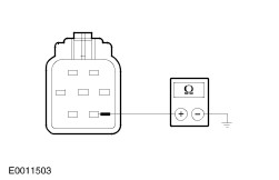
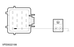
| B9: CHECK THE GROUND CONNECTION OF LEFT-HAND HEADLAMP |
| | 1 Ignition switch in position 0. |
| | 2 Measure the resistance between left-hand gas discharge lamp, connector C1146, pin 11, circuit 31-LE31 (BK), wiring harness side and ground. |
| | Is the resistance less than 2 ohms? Yes - Headlamp levelling system inoperative on both sides: GO to B10. Headlamp levelling system inoperative on the left-hand side: GO to B23. No LOCATE and RECTIFY break in circuit between gas discharge lamp and soldered connection S315 with the aid of the wiring diagrams. CHECK the operation of the system. |
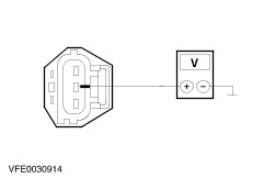
| B10: CHECK VOLTAGE SUPPLY OF REAR HEADLAMP LEVELLING SENSOR FOR OPEN CIRCUIT |
| | 1 Connect Left-hand gas discharge lamp with connector C1146 . |
| | 2 Disconnect Rear headlamp levelling sensor from connector C94 . |
| | 3 Ignition switch in position II. |
| | 4 Switch on the dipped beam. |
| | 5 Measure the voltage between rear headlamp levelling sensor, connector C94, pin 3: - Vehicles built before 10/2001: circuit 7-XL9 (YE/VT), wiring harness side and ground.
- Vehicles built from 10/2001: circuit 7-LE54 (YE/BK), wiring harness side and ground.
|
| | Is a constant voltage of 5 V displayed? Yes No - No voltage is displayed, vehicles built before 10/2001: LOCATE and RECTIFY the break in circuit 7-XL9 (YE/VT) (before 10/2001) between the gas discharge lamp and headlamp levelling sensor with the aid of the wiring diagrams. CHECK the operation of the system. - No voltage is displayed, vehicles built from 10/2001: LOCATE and RECTIFY the break in circuit 7-LE54 (YE/BK) between gas discharge lamp and headlamp levelling sensor with the aid of wiring diagrams. CHECK the operation of the system. - Battery voltage is displayed: LOCATE and RECTIFY short to battery voltage in the circuits connected to gas discharge lamp, connector C1146, pin 9 with the aid of the wiring diagrams. CHECK the operation of the system. If the concern persists, CHECK and if necessary RENEW the gas discharge lamp. CHECK the operation of the system. |
| B11: CHECK VOLTAGE SUPPLY OF FRONT HEADLAMP LEVELLING SENSOR FOR OPEN CIRCUIT |
| | 1 Ignition switch in position 0. |
| | 2 Disconnect Front headlamp levelling sensor from connector C195 . |
| | 3 Ignition switch in position II. |
| | 4 Switch on the dipped beam. |
| | 5 Measure the voltage between front headlamp levelling sensor, connector C195, pin 3: - Vehicles built before 10/2001: circuit 7-XL9A (YE/VT), wiring harness side and ground.
- Vehicles built from 10/2001: circuit 7-LE53 (YE/BU), wiring harness side and ground.
|
| | Is a constant voltage of 5 V displayed? Yes No - No voltage is displayed, vehicles built before 10/2001: LOCATE and RECTIFY break in circuit 7-XL9A (YE/VT) between gas discharge lamp and headlamp levelling sensor with the aid of the wiring diagrams. CHECK the operation of the system. - No voltage is displayed, vehicles built from 10/2001: LOCATE and RECTIFY break in circuit 7-LE53 (YE/BU) between gas discharge lamp and headlamp levelling sensor with the aid of the wiring diagrams. CHECK the operation of the system. - Battery voltage is displayed: LOCATE and RECTIFY short to battery voltage in the circuits connected to gas discharge lamp, connector C1146, pin 9 with the aid of the wiring diagrams. CHECK the operation of the system. If the concern persists, CHECK and if necessary RENEW the gas discharge lamp. CHECK the operation of the system. |
| B12: CHECK CONTROL CIRCUIT OF REAR HEADLAMP LEVELLING SENSOR FOR SHORT TO BATTERY VOLTAGE |
| | 1 Ignition switch in position 0. |
| | 2 Disconnect Left-hand gas discharge lamp from connector C1146 . |
| | 3 Ignition switch in position II. |
| | 4 Measure the voltage between rear headlamp levelling sensor, connector C94, pin 2: - Vehicles built before 10/2001: circuit 8-XL9 (WH/VT), wiring harness side and ground.
- Vehicles built from 10/2001: 8-LE54 (WH/BK), wiring harness side and ground.
|
| | Is battery voltage displayed? Yes - Vehicles built before 10/2001: LOCATE and RECTIFY short to battery voltage in circuit 8-XL9 (WH/VT) between gas discharge lamp and headlamp levelling sensor with the aid of the wiring diagrams. CHECK the operation of the system. - Vehicles built from 10/2001: LOCATE and RECTIFY short to battery voltage in circuit 8-LE54 (WH/BK) between gas discharge lamp and headlamp levelling sensor with the aid of the wiring diagrams. CHECK the operation of the system. No |
| B13: CHECK CONTROL CIRCUIT OF REAR HEADLAMP LEVELLING SENSOR FOR SHORT TO GROUND |
| | 1 Ignition switch in position 0. |
| | 2 Measure resistance between rear headlamp levelling sensor, connector C94, pin 2: - Vehicles built before 10/2001: circuit 8-XL9 (WH/VT), wiring harness side and ground.
- Vehicles built from 10/2001: circuit 8-LE54 (WH/BK), wiring harness side and ground.
|
| | Is the resistance more than 10,000 Ohms? Yes No - Vehicles built before 10/2001: LOCATE and RECTIFY short to ground in circuit 8-XL9 (WH/VT) between gas discharge lamp and headlamp levelling sensor with the aid of the wiring diagrams. CHECK the operation of the system. - Vehicles built from 10/2001: LOCATE and RECTIFY short to ground in circuit 8-LE54 (WH/BK) between gas discharge lamp and headlamp levelling sensor with the aid of the wiring diagrams. CHECK the operation of the system. |
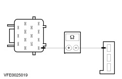
| B14: CHECK CONTROL CIRCUIT OF REAR HEADLAMP LEVELLING SENSOR FOR OPEN CIRCUIT |
| | 1 Measure resistance between left-hand gas discharge lamp, connector C1146 pin 10: - Vehicles built before 10/2001: circuit 8-XL9 (WH/VT), wiring harness side and rear headlamp levelling sensor, connector C94, pin 2, circuit 8-XL9 (WH/VT), wiring harness side.
- Vehicles built from 10/2001: circuit 8-LE54 (WH/BK), wiring harness side and rear headlamp levelling sensor, connector C94, pin 2, circuit 8-LE54 (WH/BK), wiring harness side.
|
| | Is the resistance less than 2 ohms? Yes No - Vehicles built before 10/2001: LOCATE and RECTIFY break in circuit 8-XL9 (WH/VT) between gas discharge lamp and headlamp levelling sensor with the aid of the wiring diagrams. CHECK the operation of the system. - Vehicles built from 10/2001: LOCATE and RECTIFY the break in circuit 8-LE54 (WH/BK) between gas discharge lamp and headlamp levelling sensor with the aid of wiring diagrams. CHECK the operation of the system. |
| B15: CHECK CONTROL CIRCUIT OF FRONT HEADLAMP LEVELLING SENSOR FOR SHORT TO BATTERY VOLTAGE |
| | 1 Ignition switch in position II. |
| | 2 Measure the voltage between front headlamp levelling sensor, connector C195, pin 2: - Vehicles built before 10/2001: circuit 8-XL9A (WH/VT), wiring harness side and ground.
- Vehicles built from 10/2001: circuit 8-LE53 (WH/BU), wiring harness side and ground.
|
| | Is battery voltage displayed? Yes - Vehicles built before 10/2001: LOCATE and RECTIFY short to battery voltage in circuit 8-XL9A (WH/VT) between gas discharge lamp and headlamp levelling sensor with the aid of the wiring diagrams. CHECK the operation of the system. - Vehicles built from 10/2001: LOCATE and RECTIFY short to battery voltage in circuit 8-LE53 (WH/BU) between gas discharge lamp and headlamp levelling sensor with the aid of the wiring diagrams. CHECK the operation of the system. No |
| B16: CHECK CONTROL CIRCUIT OF FRONT HEADLAMP LEVELLING SENSOR FOR SHORT TO GROUND |
| | 1 Ignition switch in position 0. |
| | 2 Measure the resistance between front headlamp levelling sensor, connector C195, pin 2: - Vehicles built before 10/2001: circuit 8-XL9A (WH/VT), wiring harness side and ground.
- Vehicles built from 10/2001: circuit 8-LE53 (WH/BU), wiring harness side and ground.
|
| | Is the resistance more than 10,000 Ohm? Yes No - Vehicles built before 10/2001: LOCATE and RECTIFY short to ground in circuit 8-XL9A (WH/VT) between gas discharge lamp and headlamp levelling sensor with the aid of the wiring diagrams. CHECK the operation of the system. - Vehicles built from 10/2001: LOCATE and RECTIFY short to ground in circuit 8-LE53 (WH/BU) between gas discharge lamp and headlamp levelling sensor with the aid of the wiring diagrams. CHECK the operation of the system. |
| B17: CHECK CONTROL CIRCUIT OF FRONT HEADLAMP LEVELLING SENSOR FOR OPEN CIRCUIT |
| | 1 Measure resistance between left-hand gas discharge lamp, connector C1146 pin 12: - Vehicles built before 10/2001: circuit 8-XL9A (WH/VT), wiring harness side and front headlamp levelling sensor, connector C195, pin 2, circuit 8-XL9A (WH/VT), wiring harness side.
- Vehicles built from 10/2001: circuit 8-LE53 (WH/BU), wiring harness side and front headlamp levelling sensor, connector C195, pin 2, circuit 8-LE53 (WH/BU), wiring harness side.
|
| | Is the resistance less than 2 ohms? Yes No - Vehicles built before 10/2001: LOCATE and RECTIFY break in circuit 8-XL9A (WH/VT) between gas discharge lamp and headlamp levelling sensor with the aid of the wiring diagrams. CHECK the operation of the system. - Vehicles built from 10/2001: LOCATE and RECTIFY break in circuit 8-LE53 (WH/BU) between gas discharge lamp and headlamp levelling sensor with the aid of the wiring diagrams. CHECK the operation of the system. |
| B18: CHECK POWER SUPPLY OF REAR HEADLAMP LEVELLING SENSOR FOR OPEN CIRCUIT |
| | 1 Measure the resistance between the left-hand gas discharge lamp: - Vehicles built before 10/2001: connector C1146, pin 9, circuit 7-XL9 (YE/VT), wiring harness side and rear headlamp levelling sensor, connector C94, pin 3, circuit 7-XL9 (YE/VT), wiring harness side.
- Vehicles built from 10/2001: connector C1146, pin 9, circuit 7-LE54 (YE/BK), wiring harness side and rear headlamp levelling sensor, connector C94, pin 3, circuit 7-LE54 (YE/BK), wiring harness side.
|
| | Is the resistance less than 2 ohms? Yes No - Vehicles built before 10/2001: LOCATE and RECTIFY break in circuit 7-XL9 (YE/VT) between gas discharge lamp and headlamp levelling sensor with the aid of the wiring diagrams. CHECK the operation of the system. - Vehicles built from 10/2001: LOCATE and RECTIFY the break in circuit 7-LE54 (YE/BK) between gas discharge lamp and headlamp levelling sensor with the aid of wiring diagrams. CHECK the operation of the system. |
| B19: CHECK POWER SUPPLY OF FRONT HEADLAMP LEVELLING SENSOR FOR OPEN CIRCUIT |
| | 1 Measure resistance between left-hand gas discharge lamp, connector C1146 pin 9: - Vehicles built before 10/2001: circuit 7-XL9 (YE/VT), wiring harness side and front headlamp levelling sensor, connector C195, pin 3, circuit 7-XL9A (YE/VT), wiring harness side and ground.
- Vehicles built from 10/2001: circuit 7-LE54 (YE/BK), wiring harness side and front headlamp levelling sensor, connector C195, pin 3, circuit 7-LE53 (YE/BU), wiring harness side and ground.
|
| | Is the resistance less than 2 ohms? Yes No - Vehicles built before 10/2001: LOCATE and RECTIFY break in circuit 7-XL9(A) (YE/VT) between gas discharge lamp and headlamp levelling sensor with the aid of the wiring diagrams. CHECK the operation of the system. - Vehicles built from 10/2001: LOCATE and RECTIFY the break in circuit 7-LE53 (YE/BK)/7-LE54 (YE/BK) between gas discharge lamp and headlamp levelling sensor with the aid of wiring diagrams. CHECK the operation of the system. |
| B20: CHECK CIRCUIT 9-XL9 (BN/WH) OR 9-LE54 (BN/YE) FOR A SHORT TO GROUND |
| | 1 Ignition switch in position 0. |
| | 2 Measure resistance between rear headlamp levelling sensor, connector C94, pin 1: - Vehicles built before 10/2001: circuit 9-XL9 (BN/WH), wiring harness side and ground.
- Vehicles built from 10/2001: circuit 9-LE54 (BN/YE) (from 10/2001), wiring harness side and ground.
|
| | Is the resistance more than 10,000 Ohms? Yes No - Vehicles built before 10/2001: LOCATE and RECTIFY short to ground in circuit 9-XL9 (BN/WH) between gas discharge lamp and headlamp levelling sensor with the aid of the wiring diagrams. CHECK the operation of the system. - Vehicles built from 10/2001: LOCATE and RECTIFY short to ground in circuit 9-LE54 (BN/YE) between gas discharge lamp and headlamp leveling sensor with the aid of the wiring diagrams. CHECK the operation of the system. |
| B21: CHECK CIRCUIT 9-XL9 (BN/WH) OR 9-LE54 (BN/YE) FOR OPEN CIRCUIT |
| | 1 Measure resistance between left-hand gas discharge lamp, connector C1146 pin 13: - Vehicles built before 10/2001: circuit 9-XL9 (BN/WH), wiring harness side and rear headlamp levelling sensor, connector C94, pin 1, circuit 9-XL9 (BN/WH), wiring harness side.
- Vehicles built from 10/2001: circuit 9-LE54 (BN/YE), wiring harness side and rear headlamp levelling sensor, connector C94, pin 1, circuit 9-LE54 (BN/YE), wiring harness side.
|
| | Is the resistance less than 2 ohms? Yes No - Vehicles built before 10/2001: LOCATE and RECTIFY break in circuit 9-XL9 (BN/WH) between gas discharge lamp and headlamp levelling sensor with the aid of the wiring diagrams. CHECK the operation of the system. - Vehicles built from 10/2001: LOCATE and RECTIFY the break in circuit 9-LE54 (BN/YE) between gas discharge lamp and headlamp levelling sensor with the aid of wiring diagrams. CHECK the operation of the system. |
| B22: CHECK CIRCUIT 9-XL9A (BN/WH) OR 9-LE53 (BN/BU) FOR OPEN CIRCUIT |
| | 1 Measure resistance between left-hand gas discharge lamp, connector C1146 pin 13: - Vehicles built before 10/2001: circuit 9-XL9 (BN/WH), wiring harness side and front headlamp levelling sensor, connector C195, pin 1, circuit 9-XL9A (BN/WH), wiring harness side.
- Vehicles built from 10/2001: circuit 9-LE54 (BN/YE), wiring harness side and front headlamp levelling sensor, connector C195, pin 1, circuit 9-LE53 (BN/BU), wiring harness side.
|
| | Is the resistance less than 2 ohms? Yes CHECK left-hand headlamp levelling sensors and gas discharge lamp and RENEW if necessary. CHECK the operation of the system. No - Vehicles built before 10/2001: LOCATE and RECTIFY break in circuit 9-XL9A (BN/WH) between gas discharge lamp and headlamp levelling sensor with the aid of the wiring diagrams. CHECK the operation of the system. - Vehicles built from 10/2001: LOCATE and RECTIFY break in circuit 9-LE53 (BN/BU) between gas discharge lamp and headlamp levelling sensor with the aid of the wiring diagrams. CHECK the operation of the system. |
| B23: CHECK LEFT-HAND HEADLAMP LEVELLING MOTOR |
| | 1 Remove the left-hand gas discharge lamp. |
| | 2 Disconnect Left-hand headlamp levelling motor . |
| | 3 Measure resistance at left-hand gas discharge lamp, connector C1146, pin 5, circuit (BU), component side and the headlamp levelling motor, circuit (BU), wiring harness side. |
| | 4 Measure resistance at left-hand gas discharge lamp, connector C1146, pin 11, circuit (BK), component side and the headlamp levelling motor, circuit (BK), wiring harness side. |
| | 5 Measure resistance at left-hand headlamp between connector C1146, pin 14, circuit (VT/YE), component side and the headlamp levelling motor, circuit (VT/YE), wiring harness side. |
| | Is the resistance in all three measurements less than 2 ohms? Yes CHECK left-hand headlamp levelling motor and RENEW if necessary. CHECK the operation of the system. If the concern persists, CHECK and if necessary RENEW the left-hand gas discharge lamp. CHECK the operation of the system. No LOCATE and RECTIFY break in circuit between headlamp levelling motor and gas discharge lamp. CHECK the operation of the system. |
| B24: CHECK POWER SUPPLY OF RIGHT-HAND GAS DISCHARGE LAMP FOR OPEN CIRCUIT |
| | 1 Ignition switch in position 0. |
| | 2 Disconnect Right-hand gas discharge lamp from connector C1147 . |
| | 3 Ignition switch in position II. |
| | 4 Switch on the dipped beam. |
| | 5 Measure the voltage between right-hand gas discharge lamp, connector C1147, pin 5, circuit 15-LE2B (GN/BU), wiring harness side and ground. |
| | Is battery voltage displayed? Yes No LOCATE and RECTIFY break in circuit between soldered connection S335 and gas discharge lamp with the aid of the wiring diagrams. CHECK the operation of the system. |
| B25: CHECK FUSE F18 (BJB) |
| | 1 Ignition switch in position 0. |
| | 2 Disconnect Fuse F18 (BJB) . |
| | 3 CHECK Fuse F18 (20 A) . |
| | Is the fuse OK.? Yes No INSTALL a new fuse F18 (20 A). If fuse blows again, LOCATE and REMEDY the short to ground with the aid of the wiring diagrams. CHECK the operation of the system. |
| B26: CHECK THE VOLTAGE AT FUSE F18 (BJB) |
| | 1 Connect Fuse F18 (BJB) . |
| | 2 Ignition switch in position II. |
| | 3 Measure the voltage between fuse F18 (20A) (BJB) and ground. |
| | Is battery voltage displayed? Yes No LOCATE AND RECTIFY the break in voltage supply of fuse F18 (BJB) with the aid of the wiring diagrams, if necessary TEST AND RENEW the BJB. CHECK the operation of the system. |
| B27: CHECK RIGHT-HAND DIPPED BEAM CONTROL CIRCUIT FOR OPEN CIRCUIT |
| | 1 Measure the voltage between right-hand gas discharge lamp, connector C1147, pin 14, circuit 15S-LE23 (GN/WH), wiring harness side and ground. |
| | Is battery voltage displayed? Yes No LOCATE and RECTIFY break in circuit between fuse F18 (BJB) and gas discharge lamp with the aid of the wiring diagrams. CHECK the operation of the system. |
| B28: CHECK GROUND CONNECTION OF RIGHT-HAND GAS DISCHARGE LAMP FOR OPEN CIRCUIT |
| | 1 Ignition switch in position 0. |
| | 2 Measure the resistance between right-hand gas discharge lamp, connector C1147, pin 11, circuit 31-LE30 (BK), wiring harness side and ground. |
| | Is the resistance less than 2 ohms? Yes No LOCATE and RECTIFY break in circuit between gas discharge lamp and soldered connection S317 with the aid of the wiring diagrams. CHECK the operation of the system. |
| B29: CHECK RIGHT-HAND GAS DISCHARGE LAMP CONTROL CIRCUIT FOR SHORT TO BATTERY VOLTAGE |
| | 1 Ignition switch in position II. |
| | 2 Measure the voltage between right-hand gas discharge lamp, connector C1147, pin 3, circuit 8-LE46 (WH/RD), wiring harness side and ground. |
| | Is battery voltage displayed? Yes LOCATE and RECTIFY short to battery voltage in circuit between left-hand gas discharge lamp and right-hand gas discharge lamp with the aid of the wiring diagrams. CHECK the operation of the system. No |
| B30: CHECK RIGHT-HAND GAS DISCHARGE LAMP CONTROL CIRCUIT FOR SHORT TO GROUND |
| | 1 Ignition switch in position 0. |
| | 2 Measure resistance between right-hand headlamp, connector C1147, pin 3, circuit 8-LE46 (WH/RD), wiring harness side and ground. |
| | Is the resistance more than 10,000 Ohm? Yes No LOCATE and RECTIFY short to ground in circuit between left-hand gas discharge lamp and right-hand gas discharge lamp with the aid of the wiring diagrams. CHECK the operation of the system. |
| B31: CHECK RIGHT-HAND GAS DISCHARGE LAMP CONTROL CIRCUIT FOR OPEN CIRCUIT |
| | 1 Disconnect Left-hand gas discharge lamp from connector C1146 . |
| | 2 Measure resistance between left-hand gas discharge lamp, connector C1146, pin 3, circuit 8-LE46 (WH/RD), wiring harness side and right-hand gas discharge lamp, connector C1147, pin 3, circuit 8-LE46 (WH/RD), wiring harness side. |
| | Is the resistance less than 2 ohms? Yes No LOCATE and RECTIFY break in circuit between left-hand gas discharge lamp and right-hand gas discharge lamp with the aid of the wiring diagrams. CHECK the operation of the system. |
| B32: CHECK RIGHT-HAND HEADLAMP LEVELLING MOTOR |
| | 1 Remove the right-hand gas discharge lamp. |
| | 2 Disconnect Right-hand headlamp levelling motor . |
| | 3 Measure resistance at right-hand gas discharge lamp, connector C1147, pin 5, circuit (BU), component side and the headlamp levelling motor, circuit (BU), wiring harness side. |
| | 4 Measure resistance at right-hand gas discharge lamp, connector C1147, pin 11, circuit (BK), component side and the headlamp levelling motor, circuit (BK), wiring harness side. |
| | 5 Measure resistance at right-hand headlamp between connector C1147, pin 14, circuit (VT/YE), component side and the headlamp levelling motor, circuit (VT/YE), wiring harness side. |
| | Is the resistance in all three measurements less than 2 ohms? Yes CHECK right-hand headlamp levelling motor and RENEW if necessary. CHECK the operation of the system. If the concern persists, CHECK and if necessary RENEW the right-hand gas discharge lamp. CHECK the operation of the system. No LOCATE and RECTIFY break in circuit between headlamp levelling motor and gas discharge lamp. CHECK the operation of the system. |