
Seats
- Make
- Ford
- Model
- Mustang Factory Service Manual
- Year
- 2007
- Section
- 501-10 Seating › Diagnosis and testing › Seats
Seats
 |
73 III Automotive Meter
105-R0057 |
 |
Vehicle Communication Module (VCM) and Integrated Diagnostic System (IDS)
software with appropriate hardware, or equivalent scan tool |
 |
Diagnostic Tool, Restraint System (2 required)
418-133 |
Restraint System Diagnostic Tool Warning
WARNING: This tool is for restraint system service only. Remove from vehicle prior to road use. Failure to remove could result in injury and possible violation of vehicle safety standards.
Principles of Operation
Power Seats
The 6-way power seat feature moves the seat in 6 possible directions: the base of the seat can be moved forward or rearward and the front and back of the seat cushion can be moved up and down independently. The power seat feature operates independent of the position of the ignition.
The power seat motors are hardwired to the seat control switch. The circuits are normally at ground through the seat control switch. An individual circuit is switched to power when a specific adjustment position is selected.
Heated Seats
The driver and passenger heated seats share a common battery feed to the heated seat relay junction box. The ignition circuit powers the logic board and illumination of the heated seat switches located internal to the electronic manual temperature control assembly (EMTC). The battery feed is used to provide voltage to the heater mats.
There are 2 power supplies to the heated seat relay. One power supply energizes the relay and heated switch LED when the key is in the RUN position and the heated seat switch is activated. This closes the relay and power is provided to the heated seat elements through the other power circuit. The heated seat module will remain ON until the heated seat switch button is depressed to cycle the heated seat module OFF or a 10-minute time-out period occurs. If ignition power is switched OFF, the heated seat module will enter an OFF state.
The driver seat cushion and backrest heater elements are wired in series as are the passenger seat cushion and backrest heater elements. The heated seat system is designed to maintain the temperature by the opening (no voltage to the heated seat mats) and closing (voltage supplied to the heated seat mats) of the bi-metallic thermostat.
Inspection and Verification
- Verify the customer concern by operating the system.
- Visually inspect for obvious signs of mechanical or electrical damage.
Visual Inspection Chart Mechanical Electrical - Front seat track
- Seat at limit(s) of travel
- Seat tracks obstructed or damaged
- Power lumbar assembly damaged
- Heated seat fuse bussed electrical center (BEC) fuse 66 (25A)
- Driver power seat and lumbar (BEC) fuse 14 (30A)
- Passenger power seat (BEC) fuse 15 (30A)
- Loose, corroded or damaged connectors
- Seat control switch
- Heated seat switch (internal to EMTC)
- Heated seat relays
- Lumbar seat control switch
- Heat seat cushion element
- Heat seat backrest element
- If an obvious cause for an observed or reported concern is found, correct the cause (if possible) before proceeding to the next step.
- If the concern is not visually evident, verify the symptom. GO to Symptom Chart.
Symptom Chart
Refer to the Wiring Diagram manual for the connector numbers cited in the pinpoint tests.
| Condition | Possible Sources | Action |
|---|---|---|
|
|
|
|
|
|
|
|
|
|
|
|
|
|
|
|
|
|
|
|
|
|
|
|
|
|
|
|
|
|
|
|
Pinpoint Tests
Refer to Inspection and Verification and the Symptom Chart for direction to the appropriate Pinpoint Test.
Pinpoint Test A: The Power Seat Is Inoperative — Driver
Refer to Wiring Diagrams Cell 120, Seating for schematic and connector information.
Normal Operation
The seat control switch is powered by battery voltage on circuit 566 (DG) and is supplied ground on circuit 1205 (BK).
Possible Causes
An inoperative power seat can be caused by:
- a fuse.
- wiring, terminals or connectors.
- a faulty power seat switch.
PINPOINT TEST A: THE POWER SEAT IS INOPERATIVE — DRIVER
| Test Step | Result / Action to Take |
|---|---|
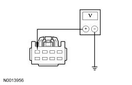
| A1 CHECK VOLTAGE TO SEAT CONTROL SWITCH CIRCUIT 566 (DG) | |
|
Yes GO to A2. No VERIFY bussed electrical center (BEC) fuse 14 (30A) is OK. If OK, REPAIR the circuit. TEST the system for normal operation. For vehicles equipped with seat side air bags, DISCONNECT the battery ground cable. DISCONNECT the restraint system diagnostic tool from driver seat side air bag module C367. CONNECT driver seat side air bag module C367. REPOWER the SRS. REFER to Section 501-20B. |
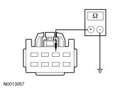
| A2 CHECK SEAT CONTROL SWITCH CIRCUIT 1205 (BK) FOR AN OPEN | |
|
Yes INSTALL a new seat control switch. TEST the system for normal operation. For vehicles equipped with seat side air bags, DISCONNECT the battery ground cable. DISCONNECT the restraint system diagnostic tool from driver seat side air bag module C367. CONNECT driver seat side air bag module C367. REPOWER the SRS. REFER to Section 501-20B. No REPAIR the circuit. TEST the system for normal operation. For vehicles equipped with seat side air bags, DISCONNECT the battery ground cable. DISCONNECT the restraint system diagnostic tool from driver seat side air bag module C367. CONNECT driver seat side air bag module C367. REPOWER the SRS. REFER to Section 501-20B. |
Pinpoint Test B: The Power Seat Is Inoperative — Passenger
Refer to Wiring Diagrams Cell 120, Seating for schematic and connector information.
Normal Operation
The seat control switch is powered by battery voltage on circuit 1462 (RD/WH) and is supplied ground on circuit 1205 (BK).
Possible Causes
An inoperative power seat can be caused by:
- a fuse.
- wiring, terminals or connectors.
- a faulty power seat switch.
PINPOINT TEST B: THE POWER SEAT IS INOPERATIVE — PASSENGER
| Test Step | Result / Action to Take |
|---|---|
| B1 CHECK THE VOLTAGE TO SEAT CONTROL SWITCH CIRCUIT 1462 (RD/WH) | |
|
Yes GO to B2. No VERIFY bussed electrical center (BEC) fuse 15 (30A) is OK. If OK, REPAIR the circuit. TEST the system for normal operation. For vehicles equipped with seat side air bags, DISCONNECT the battery ground cable. DISCONNECT the restraint system diagnostic tool from passenger seat side air bag module C337. CONNECT passenger seat side air bag module C337. REPOWER the SRS. REFER to Section 501-20B. |
| B2 CHECK SEAT CONTROL SWITCH CIRCUIT 1205 (BK) FOR AN OPEN | |
|
Yes INSTALL a new seat control switch. TEST the system for normal operation. For vehicles equipped with seat side air bags, DISCONNECT the battery ground cable. DISCONNECT the restraint system diagnostic tool from passenger seat side air bag module C337. CONNECT passenger seat side air bag module C337. REPOWER the SRS. REFER to Section 501-20B. No REPAIR the circuit. TEST the system for normal operation. For vehicles equipped with seat side air bags, DISCONNECT the battery ground cable. DISCONNECT the restraint system diagnostic tool from passenger seat side air bag module C337. CONNECT passenger seat side air bag module C337. REPOWER the SRS. REFER to Section 501-20B. |
Pinpoint Test C: The Power Seat Moves But Is Noisy
Normal Operation
The power seat should move quietly during operation. Some noise is acceptable.
Possible Causes
A noisy power seat can be caused by:
- a misaligned seat track.
- a faulty seat track component.
- an object obstructing seat movement.
PINPOINT TEST C: THE POWER SEAT MOVES BUT IS NOISY
Pinpoint Test D: The Power Seat Moves But Is Loose
Normal Operation
The power seat movement should be smooth and the seat cushion should not rock during or after operation.
Possible Causes
A loose power seat can be caused by:
- loose fastening hardware.
- a faulty seat track component.
PINPOINT TEST D: THE POWER SEAT MOVES BUT IS LOOSE
Pinpoint Test E: The Power Seat Does Not Make Full Travel
Normal Operation
The power seat should travel fully horizontal (forward/rearward) and vertical (front up/down and rear up/down).
Possible Causes
A power seat that does not make full travel can be caused by:
- an obstruction.
- a faulty seat track component.
PINPOINT TEST E: THE POWER SEAT DOES NOT MAKE FULL TRAVEL
| Test Step | Result / Action to Take |
|---|---|
| E1 CHECK FOR AN OBSTRUCTION IN THE SEAT TRACK | |
|
Yes REMOVE the obstruction(s) and LUBRICATE the track(s). TEST the system for normal operation. REPOWER the SRS. REFER to Section 501-20B. No IDENTIFY the cause and REPAIR as necessary. TEST the system for normal operation. REPOWER the SRS. REFER to Section 501-20B. |
Pinpoint Test F : The Power Seat Does Not Move Horizontally/Vertically — Driver
Refer to Wiring Diagrams Cell 120, Seating for schematic and connector information.
Normal Operation
The seat control switch is powered by battery voltage on circuit 566 (DG) and is supplied ground on circuit 1205 (BK). When pressed, the seat control switch supplies that voltage and ground to a power seat track motor to move the seat. When pressed in the opposite direction, the power seat switch reverses the polarity to the power seat track motor, which moves the seat in the opposite direction. There are 3 power seat track motors that combine to move the seat horizontally (forward/reverse) and vertically (front up/down and rear up/down).
Possible Causes
A power seat that does not move horizontally and/or vertically can be caused by:
- wiring, terminals or connectors.
- a faulty seat control switch.
- a faulty seat track motor.
PINPOINT TEST F: THE POWER SEAT DOES NOT MOVE HORIZONTALLY/VERTICALLY — DRIVER
| Test Step | Result / Action to Take |
|---|---|
| F1 DETERMINE WHICH DIRECTION HAS FAILED | |
|
Yes GO to F2. No GO to F9. |
| F2 DETERMINE POWER SEAT TILTING FAILURE | |
|
Yes If only the forward tilting operates, GO to F3 . If only the rearward tilting operates, GO to F6 . No INSTALL a new seat control switch. TEST the system for normal operation. For vehicles equipped with seat side air bags, DISCONNECT the battery ground cable. DISCONNECT the restraint system diagnostic tool from driver seat side air bag module C367. CONNECT driver seat side air bag module C367. REPOWER the SRS. REFER to Section 501-20B. |
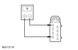
| F3 CHECK VOLTAGE TO THE REAR HEIGHT MOTOR | |
|
Yes INSTALL a new driver seat track assembly. TEST the system for normal operation. For vehicles equipped with seat side air bags, DISCONNECT the battery ground cable. DISCONNECT the restraint system diagnostic tool from driver seat side air bag module C367. CONNECT driver seat side air bag module C367. REPOWER the SRS. REFER to Section 501-20B. No GO to F4. |
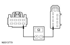
| F4 CHECK CIRCUIT 983 (RD/LG) FOR AN OPEN | |
|
Yes GO to F5. No REPAIR the circuit. TEST the system for normal operation. For vehicles equipped with seat side air bags, DISCONNECT the battery ground cable. DISCONNECT the restraint system diagnostic tool from driver seat side air bag module C367. CONNECT driver seat side air bag module C367. REPOWER the SRS. REFER to Section 501-20B. |
| F5 CHECK CIRCUIT 982 (YE/LG) FOR AN OPEN | |
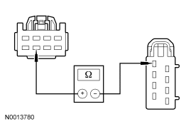
|
Yes INSTALL a new driver seat control switch. TEST the system for normal operation. For vehicles equipped with seat side air bags, DISCONNECT the battery ground cable. DISCONNECT the restraint system diagnostic tool from driver seat side air bag module C367. CONNECT driver seat side air bag module C367. REPOWER the SRS. REFER to Section 501-20B. No REPAIR the circuit. TEST the system for normal operation. For vehicles equipped with seat side air bags, DISCONNECT the battery ground cable. DISCONNECT the restraint system diagnostic tool from driver seat side air bag module C367. CONNECT driver seat side air bag module C367. REPOWER the SRS. REFER to Section 501-20B. |
| F6 CHECK VOLTAGE TO THE FRONT HEIGHT MOTOR | |
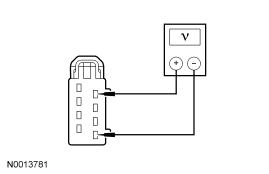
|
Yes INSTALL a new driver seat track assembly. TEST the system for normal operation. For vehicles equipped with seat side air bags, DISCONNECT the battery ground cable. DISCONNECT the restraint system diagnostic tool from driver seat side air bag module C367. CONNECT driver seat side air bag module C367. REPOWER the SRS. REFER to Section 501-20B. No GO to F7. |
| F7 CHECK CIRCUIT 979 (RD/LB) FOR AN OPEN | |
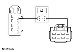
|
Yes GO to F8. No REPAIR the circuit. TEST the system for normal operation. For vehicles equipped with seat side air bags, DISCONNECT the battery ground cable. DISCONNECT the restraint system diagnostic tool from driver seat side air bag module C367. CONNECT driver seat side air bag module C367. REPOWER the SRS. REFER to Section 501-20B. |
| F8 CHECK CIRCUIT 990 (YE/LB) FOR AN OPEN | |
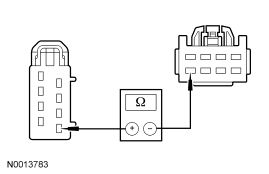
|
Yes INSTALL a new driver seat control switch. TEST the system for normal operation. For vehicles equipped with seat side air bags, DISCONNECT the battery ground cable. DISCONNECT the restraint system diagnostic tool from driver seat side air bag module C367. CONNECT driver seat side air bag module C367. REPOWER the SRS. REFER to Section 501-20B. No REPAIR the circuit. TEST the system for normal operation. For vehicles equipped with seat side air bags, DISCONNECT the battery ground cable. DISCONNECT the restraint system diagnostic tool from driver seat side air bag module C367. CONNECT driver seat side air bag module C367. REPOWER the SRS. REFER to Section 501-20B. |
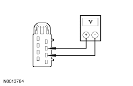
| F9 CHECK VOLTAGE TO THE HORIZONTAL MOTOR | |
|
Yes INSTALL a new driver seat track assembly. TEST the system for normal operation. For vehicles equipped with seat side air bags, DISCONNECT the battery ground cable. DISCONNECT the restraint system diagnostic tool from driver seat side air bag module C367. CONNECT driver seat side air bag module C367. REPOWER the SRS. REFER to Section 501-20B. No GO to F10. |
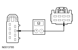
| F10 CHECK CIRCUIT 981 (RD/WH) FOR AN OPEN | |
|
Yes GO to F11. No REPAIR the circuit. TEST the system for normal operation. For vehicles equipped with seat side air bags, DISCONNECT the battery ground cable. DISCONNECT the restraint system diagnostic tool from driver seat side air bag module C367. CONNECT driver seat side air bag module C367. REPOWER the SRS. REFER to Section 501-20B. |
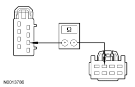
| F11 CHECK CIRCUIT 980 (YE/WH) FOR AN OPEN | |
|
Yes INSTALL a new driver seat control switch. TEST the system for normal operation. For vehicles equipped with seat side air bags, DISCONNECT the battery ground cable. DISCONNECT the restraint system diagnostic tool from driver seat side air bag module C367. CONNECT driver seat side air bag module C367. REPOWER the SRS. REFER to Section 501-20B. No REPAIR the circuit. TEST the system for normal operation. For vehicles equipped with seat side air bags, DISCONNECT the battery ground cable. DISCONNECT the restraint system diagnostic tool from driver seat side air bag module C367. CONNECT driver seat side air bag module C367. REPOWER the SRS. REFER to Section 501-20B. |
Pinpoint Test G: The Power Seat Does Not Move Horizontally/Vertically — Passenger
Refer to Wiring Diagrams Cell 120, Seating for schematic and connector information.
Normal Operation
The seat control switch is powered by battery voltage on circuit 1462 (RD/WH) and is supplied ground on circuit 1205 (BK). When pressed, the seat control switch supplies that voltage and ground to a power seat track motor to move the seat. When pressed in the opposite direction, the power seat switch reverses the polarity to the power seat track motor, which moves the seat in the opposite direction. There are 3 power seat track motors that combine to move the seat horizontally (forward/reverse) and vertically (front up/down and rear up/down).
Possible Causes
A power seat that does not move horizontally and/or vertically can be caused by:
- wiring, terminals or connectors.
- a faulty seat control switch.
- a faulty seat track motor.
PINPOINT TEST G: THE POWER SEAT DOES NOT MOVE HORIZONTALLY/VERTICALLY — PASSENGER
| Test Step | Result / Action to Take |
|---|---|
| G1 DETERMINE WHICH DIRECTION HAS FAILED | |
|
Yes GO to G2. No GO to G9. |
| G2 DETERMINE POWER SEAT TILTING FAILURE | |
|
Yes If only the rearward tilting operates, GO to G3 . If only the forward tilting operates, GO to G6 . No INSTALL a new seat control switch. TEST the system for normal operation. For vehicles equipped with seat side air bags, DISCONNECT the battery ground cable. DISCONNECT the restraint system diagnostic tool from passenger seat side air bag module C337. CONNECT passenger seat side air bag module C337. REPOWER the SRS. REFER to Section 501-20B. |
| G3 CHECK VOLTAGE TO THE FRONT HEIGHT MOTOR | |
|
Yes INSTALL a new passenger seat track assembly. TEST the system for normal operation. For vehicles equipped with seat side air bags, DISCONNECT the battery ground cable. DISCONNECT the restraint system diagnostic tool from passenger seat side air bag module C337. CONNECT passenger seat side air bag module C337. REPOWER the SRS. REFER to Section 501-20B. No GO to G4. |
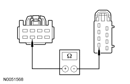
| G4 CHECK CIRCUIT 984 (YE/LB) FOR AN OPEN | |
|
Yes GO to G5. No REPAIR the circuit. TEST the system for normal operation. For vehicles equipped with seat side air bags, DISCONNECT the battery ground cable. DISCONNECT the restraint system diagnostic tool from passenger seat side air bag module C337. CONNECT passenger seat side air bag module C337. REPOWER the SRS. REFER to Section 501-20B. |
| G5 CHECK CIRCUIT 985 (RD/LB) FOR AN OPEN | |
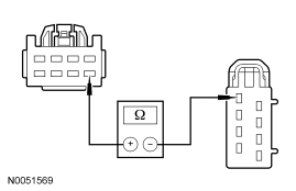
|
Yes INSTALL a new passenger seat control switch. TEST the system for normal operation. For vehicles equipped with seat side air bags, DISCONNECT the battery ground cable. DISCONNECT the restraint system diagnostic tool from passenger seat side air bag module C337. CONNECT passenger seat side air bag module C337. REPOWER the SRS. REFER to Section 501-20B. No REPAIR the circuit. TEST the system for normal operation. For vehicles equipped with seat side air bags, DISCONNECT the battery ground cable. DISCONNECT the restraint system diagnostic tool from driver seat side air bag module C367. CONNECT driver seat side air bag module C367. REPOWER the SRS. REFER to Section 501-20B. |
| G6 CHECK VOLTAGE TO THE REAR HEIGHT MOTOR | |
|
Yes INSTALL a new passenger seat track assembly. TEST the system for normal operation. For vehicles equipped with seat side air bags, DISCONNECT the battery ground cable. DISCONNECT the restraint system diagnostic tool from passenger seat side air bag module C337. CONNECT passenger seat side air bag module C337. REPOWER the SRS. REFER to Section 501-20B. No GO to G7. |
| G7 CHECK CIRCUIT 988 (YE/LG) FOR AN OPEN | |
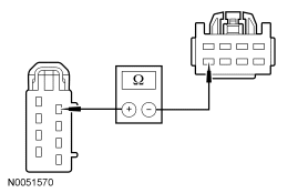
|
Yes GO to G8. No REPAIR the circuit. TEST the system for normal operation. For vehicles equipped with seat side air bags, DISCONNECT the battery ground cable. DISCONNECT the restraint system diagnostic tool from passenger seat side air bag module C337. CONNECT passenger seat side air bag module C337. REPOWER the SRS. REFER to Section 501-20B. |
| G8 CHECK CIRCUIT 989 (RD/LG) FOR AN OPEN | |
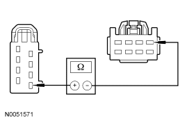
|
Yes INSTALL a new passenger seat control switch. TEST the system for normal operation. For vehicles equipped with seat side air bags, DISCONNECT the battery ground cable. DISCONNECT the restraint system diagnostic tool from passenger seat side air bag module C337. CONNECT driver seat side air bag module C337. REPOWER the SRS. REFER to Section 501-20B. No REPAIR the circuit. TEST the system for normal operation. For vehicles equipped with seat side air bags, DISCONNECT the battery ground cable. DISCONNECT the restraint system diagnostic tool from passenger seat side air bag module C337. CONNECT passenger seat side air bag module C337. REPOWER the SRS. REFER to Section 501-20B. |
| G9 CHECK VOLTAGE TO THE HORIZONTAL MOTOR | |
|
Yes INSTALL a new passenger seat track assembly. TEST the system for normal operation. For vehicles equipped with seat side air bags, DISCONNECT the battery ground cable. DISCONNECT the restraint system diagnostic tool from passenger seat side air bag module C337. CONNECT passenger seat side air bag module C337. REPOWER the SRS. REFER to Section 501-20B. No GO to G10. |
| G10 CHECK CIRCUIT 987 (RD/WH) FOR AN OPEN | |
|
Yes GO to G11. No REPAIR the circuit. TEST the system for normal operation. For vehicles equipped with seat side air bags, DISCONNECT the battery ground cable. DISCONNECT the restraint system diagnostic tool from passenger seat side air bag module C337. CONNECT passenger seat side air bag module C337. REPOWER the SRS. REFER to Section 501-20B. |
| G11 CHECK CIRCUIT 986 (YE/WH) FOR AN OPEN | |
|
Yes INSTALL a new passenger seat control switch. TEST the system for normal operation. For vehicles equipped with seat side air bags, DISCONNECT the battery ground cable. DISCONNECT the restraint system diagnostic tool from passenger seat side air bag module C337. CONNECT passenger seat side air bag module C337. REPOWER the SRS. REFER to Section 501-20B. No REPAIR the circuit. TEST the system for normal operation. For vehicles equipped with seat side air bags, DISCONNECT the battery ground cable. DISCONNECT the restraint system diagnostic tool from passenger seat side air bag module C337. CONNECT passenger seat side air bag module C337. REPOWER the SRS. REFER to Section 501-20B. |
Pinpoint Test H: The Power Lumbar Is Inoperative
Refer to Wiring Diagrams Cell 120, Seating for schematic and connector information.
Normal Operation
The lumbar control switch is powered by battery voltage on circuit 566 (DG) and is supplied ground on circuit 1205 (BK). When the knob of the lumbar control switch is pressed, voltage and ground are supplied to the power lumbar motor. When pressing the lumbar knob in the opposite direction, the lumbar control switch reverses the polarity to the power lumbar motor, which moves the lumbar mechanism in the opposite direction.
Possible Causes
An inoperative power lumbar can be caused by:
- wiring, terminals or connectors.
- a faulty lumbar control switch.
- a faulty power lumbar motor assembly.
PINPOINT TEST H: THE POWER LUMBAR IS INOPERATIVE
| Test Step | Result / Action to Take |
|---|---|
| H1 CHECK CIRCUIT 566 (DG) FOR AN OPEN | |
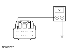
|
Yes GO to H2. No VERIFY bussed electrical center (BEC) fuse 14 (30A) is OK. If OK, REPAIR the circuit. TEST the system for normal operation. For vehicles equipped with seat side air bags, DISCONNECT the battery ground cable. DISCONNECT the restraint system diagnostic tool from driver seat side air bag module C367. CONNECT driver seat side air bag module C367. REPOWER the SRS. REFER to Section 501-20B. |
| H2 CHECK CIRCUIT 1205 (BK) FOR AN OPEN | |
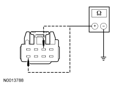
|
Yes GO to H3. No REPAIR the circuit. TEST the system for normal operation. For vehicles equipped with seat side air bags, DISCONNECT the battery ground cable. DISCONNECT the restraint system diagnostic tool from driver seat side air bag module C367. CONNECT driver seat side air bag module C367. REPOWER the SRS. REFER to Section 501-20B. |
| H3 CHECK THE LUMBAR MOTOR | |
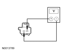
|
Yes INSTALL a new power lumbar assembly. TEST the system for normal operation. For vehicles equipped with seat side air bags, DISCONNECT the battery ground cable. DISCONNECT the restraint system diagnostic tool from driver seat side air bag module C367. CONNECT driver seat side air bag module C367. REPOWER the SRS. REFER to Section 501-20B. No GO to H4. |
| H4 CHECK CIRCUIT 1094 (PK) AND CIRCUIT 1097 (BN) FOR A SHORT TO GROUND | |
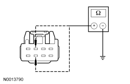
|
Yes GO to H5. No REPAIR the circuit. TEST the system for normal operation. For vehicles equipped with seat side air bags, DISCONNECT the battery ground cable. DISCONNECT the restraint system diagnostic tool from driver seat side air bag module C367. CONNECT driver seat side air bag module C367. REPOWER the SRS. REFER to Section 501-20B. |
| H5 CHECK CIRCUIT 1094 (PK) AND CIRCUIT 1097 (BN) FOR AN OPEN | |
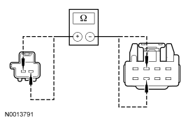
|
Yes INSTALL a new lumbar control switch. TEST the system for normal operation. For vehicles equipped with seat side air bags, DISCONNECT the battery ground cable. DISCONNECT the restraint system diagnostic tool from driver seat side air bag module C367. CONNECT driver seat side air bag module C367. REPOWER the SRS. REFER to Section 501-20B. No REPAIR the circuit. TEST the system for normal operation. For vehicles equipped with seat side air bags, DISCONNECT the battery ground cable. DISCONNECT the restraint system diagnostic tool from driver seat side air bag module C367. CONNECT driver seat side air bag module C367. REPOWER the SRS. REFER to Section 501-20B. |
Pinpoint Test I: The Heated Seat Is Inoperative
Normal Operation
The electronic manual temperature control (EMTC) module includes the heated seat control buttons and indicators. The heated seat system will function when the EMTC module is ON or OFF. There is a relay box located behind the headlamp switch area containing 2 micro relays for the driver and passenger heated seats. There are 2 power supplies to the heated seat relay. One power supply energizes the relay and heated switch LED when the key is in the run position and the heated seat switch is activated. This closes the relay and power is provided to the heated seat elements through the other power circuit. If the heated seat switch is ON when the ignition is turned OFF, the heated seat switch will be ON when the ignition is turned back ON.
Possible Causes
An inoperative heated seat can be caused by:
- fuse(s).
- wiring, terminals or connectors.
- a faulty heated seat switch (EMTC).
- a faulty heated seat relay.
- a faulty heated seat element.
PINPOINT TEST I: THE HEATED SEAT IS INOPERATIVE
| Test Step | Result / Action to Take |
|---|---|
| I1 CHECK HEATED SEAT SWITCH OPERATION | |
|
Yes If both indicators illuminate: For driver seat, Go To Pinpoint Test J. For passenger seat, Go To Pinpoint Test K. No GO to I2. |
| I2 CHECK THE HEATED SEAT POWER CIRCUITS | |
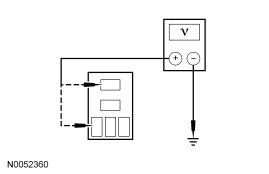
|
Yes GO to I3. No VERIFY bussed electrical center (BEC) fuse 66 (25A) is OK. If OK, REPAIR circuit 1048 (LB/WH). TEST the system for normal operation. |
| I3 CHECK THE EMTC MODULE FOR DTCs | |
|
Yes REFER to Section 412-00 to diagnose the EMTC fault. No INSTALL a new EMTC module. TEST the system for normal operation. |
Pinpoint Test J: The Heated Seat Is Inoperative—Seat Does Not Heat But The Heated Seat Indicator Illuminates When Pressed—Driver
Normal Operation
There are 2 power supplies to the heated seat relay. One power supply energizes the relay and heated switch LED when the key is in the run position and the heated seat switch is activated. This closes the relay and power is provided to the heated seat elements through the other power circuit. If the heated seat switch is ON when the ignition is turned OFF, the heated seat switch will be ON when the ignition is turned back ON.
Possible Causes
An inoperative heated seat can be caused by:
- wiring, terminals or connectors.
- a faulty heated seat switch (EATC module).
- a faulty heated seat relay.
- a faulty heated seat mat.
PINPOINT TEST J: THE HEATED SEAT IS INOPERATIVE—SEAT DOES NOT HEAT BUT THE HEATED SEAT INDICATOR ILLUMINATES WHEN PRESSED — DRIVER
| Test Step | Result / Action to Take |
|---|---|
| J1 CHECK CIRCUIT 1064 (YE/LB) FOR AN OPEN | |
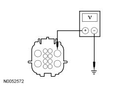
|
Yes GO to J3. No GO to J2. |
| J2 CHECK THE HEATED SEAT RELAY | |
|
Yes INSTALL a new heated seat relay. TEST the system for normal operation. For vehicles equipped with seat side air bags, DISCONNECT the battery ground cable. DISCONNECT the restraint system diagnostic tool from driver seat side air bag module C367. CONNECT driver seat side air bag module C367. REPOWER the SRS. REFER to Section 501-20B. No GO to J3. |
| J3 CHECK CIRCUIT 1064 (YE/LB) FOR AN OPEN | |
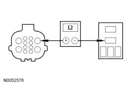
|
Yes GO to J4. No REPAIR circuit 1064 (YE/LB). TEST the system for normal operation. For vehicles equipped with seat side air bags, DISCONNECT the battery ground cable. DISCONNECT the restraint system diagnostic tool from driver seat side air bag module C367. CONNECT driver seat side air bag module C367. REPOWER the SRS. REFER to Section 501-20B. |
| J4 CHECK CIRCUIT 1205 (BK) FOR AN OPEN | |
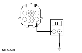
|
Yes GO to J5. No REPAIR circuit 1205 (BK). TEST the system for normal operation. For vehicles equipped with seat side air bags, DISCONNECT the battery ground cable. DISCONNECT the restraint system diagnostic tool from driver seat side air bag module C367. CONNECT driver seat side air bag module C367. REPOWER the SRS. REFER to Section 501-20B. |
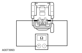
| J5 CHECK HEATED SEAT CUSHION ELEMENT FOR AN OPEN | |
|
Yes GO to J6. No INSTALL a new heated seat cushion element. REFER to Seat Cushion Cover — Front. TEST the system for normal operation. For vehicles equipped with seat side air bags, DISCONNECT the battery ground cable. DISCONNECT the restraint system diagnostic tool from driver seat side air bag module C367. CONNECT driver seat side air bag module C367. REPOWER the SRS. REFER to Section 501-20B. |
| J6 CHECK HEATED SEAT BACKREST ELEMENT FOR AN OPEN | |
|
Yes REPAIR seat harness. TEST the system for normal operation. For vehicles equipped with seat side air bags, DISCONNECT the battery ground cable. DISCONNECT the restraint system diagnostic tool from driver seat side air bag module C367. CONNECT driver seat side air bag module C367. REPOWER the SRS. REFER to Section 501-20B. No INSTALL a new heated seat cushion element. REFER to Seat Cushion Cover — Front. TEST the system for normal operation. For vehicles equipped with seat side air bags, DISCONNECT the battery ground cable. DISCONNECT the restraint system diagnostic tool from driver seat side air bag module C367. CONNECT driver seat side air bag module C367. REPOWER the SRS. REFER to Section 501-20B. |
Pinpoint Test K: The Heated Seat Is Inoperative—Seat Does Not Heat But The Heated Seat Indicator Illuminates When Pressed—Passenger
Normal Operation
There are 2 power supplies to the heated seat relay. One power supply energizes the relay and heated switch LED when the key is in the run position and the heated seat switch is activated. This closes the relay and power is provided to the heated seat elements through the other power circuit. If the heated seat switch is ON when the ignition is turned OFF, the heated seat switch will be ON when the ignition is turned back ON.
Possible Causes
An inoperative heated seat can be caused by:
- wiring, terminals or connectors.
- a faulty heated seat switch (EMTC module).
- a faulty heated seat relay.
- a faulty heated seat element.
PINPOINT TEST K: THE HEATED SEAT IS INOPERATIVE—SEAT DOES NOT HEAT BUT THE HEATED SEAT INDICATOR ILLUMINATES WHEN PRESSED—PASSENGER
| Test Step | Result / Action to Take |
|---|---|
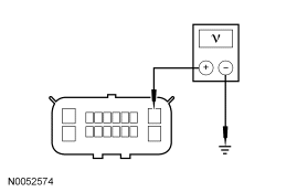
| K1 CHECK CIRCUIT 2124 (YE/LB) FOR AN OPEN | |
|
Yes GO to K3. No GO to K2. |
| K2 CHECK THE HEATED SEAT RELAY | |
|
Yes INSTALL a new heated seat relay. Test the system for normal operation. For vehicles equipped with seat side air bags, DISCONNECT the battery ground cable. DISCONNECT the restraint system diagnostic tool from passenger seat side air bag module C337. CONNECT passenger seat side air bag module C337. REPOWER the SRS. REFER to Section 501-20B. No GO to K3. |
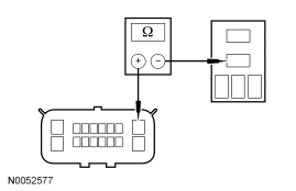
| K3 CHECK CIRCUIT 2124 (YE/LB) FOR AN OPEN | |
|
Yes GO to K4. No REPAIR circuit 2124 (YE/LB). TEST the system for normal operation. For vehicles equipped with seat side air bags, DISCONNECT the battery ground cable. DISCONNECT the restraint system diagnostic tool from driver seat side air bag module C367. CONNECT driver seat side air bag module C367. REPOWER the SRS. REFER to Section 501-20B. |
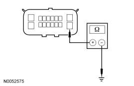
| K4 CHECK CIRCUIT 1205 (BK) FOR AN OPEN | |
|
Yes GO to K5. No REPAIR circuit 1205 (BK). TEST the system for normal operation. For vehicles equipped with seat side air bags, DISCONNECT the battery ground cable. DISCONNECT the restraint system diagnostic tool from passenger seat side air bag module C337. CONNECT passenger seat side air bag module C337. REPOWER the SRS. REFER to Section 501-20B. |
| K5 CHECK HEATED SEAT CUSHION ELEMENT FOR AN OPEN | |
|
Yes GO to K6. No INSTALL a new heated seat cushion. REFER to Seat Cushion Cover — Front. TEST the system for normal operation. For vehicles equipped with seat side air bags, DISCONNECT the battery ground cable. DISCONNECT the restraint system diagnostic tool from passenger seat side air bag module C337. CONNECT passenger seat side air bag module C337. REPOWER the SRS. REFER to Section 501-20B. |
| K6 CHECK HEATED SEAT BACKREST ELEMENT FOR AN OPEN | |
|
Yes REPAIR the seat harness. TEST the system for normal operation. For vehicles equipped with seat side air bags, DISCONNECT the battery ground cable. DISCONNECT the restraint system diagnostic tool from passenger seat side air bag module C337. CONNECT passenger seat side air bag module C337. REPOWER the SRS. REFER to Section 501-20B. No INSTALL a new heated seat Backrest. REFER to Seat Backrest — Front. TEST the system for normal operation. For vehicles equipped with seat side air bags, DISCONNECT the battery ground cable. DISCONNECT the restraint system diagnostic tool from passenger seat side air bag module C337. CONNECT passenger seat side air bag module C337. REPOWER the SRS. REFER to Section 501-20B. |
Parts & tools for this job For 2007 Ford Mustang
- TOOLTrim removal tool kitSearch: trim removal tool kit
- PARTTouch-up paintSearch: Ford touch up paint
- PARTPanel clip assortmentSearch: Ford panel clips assortment
Links open Amazon search results in a new tab. As an Amazon Associate I earn from qualifying purchases.