
Mustang Cobra V8-281 4.6L DOHC VIN V MFI (1997)
Connecting Rod: Service and Repair
Removal and Installation
Removal
REMOVAL
1. Remove engine.
2. Loosen four bolts retaining water pump pulley (8509) to water pump (8501). (Do not remove bolts.)
3. Release drive belt tensioner (6B209) and remove accessory drive belt (8620).
4. Disconnect water bypass tube to water thermostat housing hose at water bypass tube. Remove hose and water thermostat housing assembly.
5. Disconnect fuel charging wiring (9D930) from A/C compressor (19703).
6. Remove eight retaining nuts on RH and LH ignition wire covers and remove ignition wire covers.
CAUTION: Do not pull on ignition wires as the ignition wire may separate from the connector in the ignition wire boot.
7. Disconnect ignition wires from spark plugs (12405) with a gentle twist/pull motion on the ignition wire boot.
8. Disconnect all ignition wires from both ignition coils (12029).
9. Detach two center ignition wire separators (12297) from generator mounting bracket (10153).
10. Remove ignition wires and ignition wire separators as an assembly.
11. Disconnect generator wiring harness from generator (GEN)(10300) at B+ terminal and disconnect stator connector plug. Disconnect wiring
harness retaining clip from generator mounting bracket.
12. Remove bolts attaching generator mounting bracket to generator and intake manifold (9424). Remove generator mounting bracket.
13. Remove four loosened water pump pulley bolts and remove water pump pulley.
14. Disconnect engine wiring harness connector from power steering pump (3A674).
15. Remove power steering reservoir from the LH ignition coil mounting bracket.
16. Remove four bolts retaining power steering pump to engine front cover (6019) and cylinder block (6010).
17. Disconnect fuel charging wiring from both ECT sensor and water temperature indicator sender unit connections at bottom of water bypass tube.
18. Remove two retaining nuts from water bypass tube hold-down braces to intake manifold studs and remove water bypass tube.
19. Remove two bolts retaining generator to cylinder block and remove generator.
20. Disconnect wiring harness from EGR backpressure transducer. Remove heat shield and two bolts retaining EGR backpressure transducer bracket
to upper intake manifold and remove bracket.
21. Remove three bolts retaining heater water hose (18472) to rear of RH cylinder head (6049) and remove heater water hose.
22. Disconnect main emission vacuum control connector (9E498) from fuel pressure regulator (9C968), intake manifold vacuum connection EGR
valve (EGR valve)(9D475) and EGR vacuum regulator solenoid and position main emission vacuum control connector out of the way.
23. Remove positive crankcase ventilation valve (PCV)(6A666) and crankcase vent connector and hose (6C324) from LH valve cover (6582) and
disconnect crankcase vent connector and hose and idle air control valve inlet tube (9H308) from upper intake manifold.
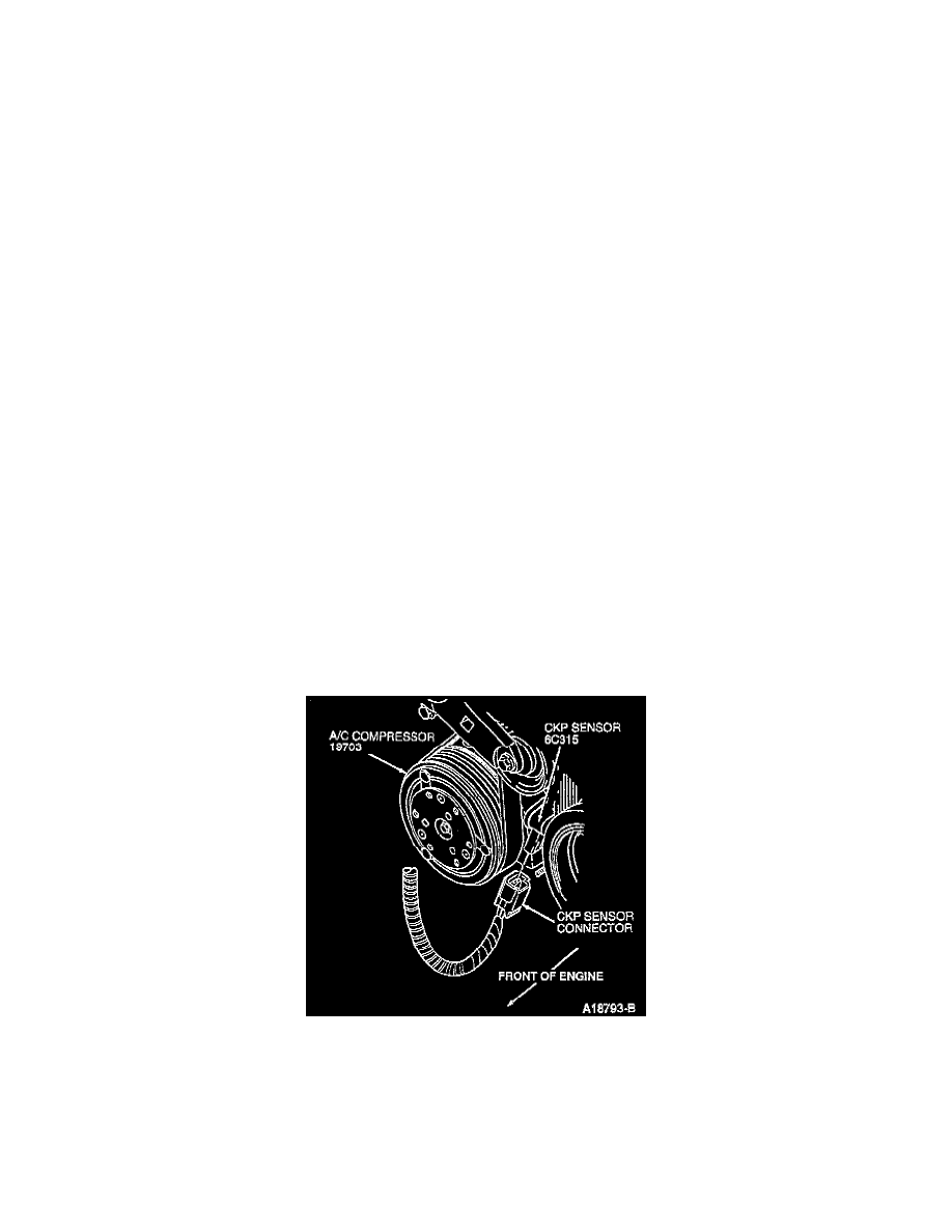
24. Disconnect fuel charging wiring from camshaft position sensor (CMP)(6B288), oil pressure sensor (9278), crankshaft position sensor (CKP)
(6C315), both ignition coils and both radio ignition interference capacitors (18801).
25. Disconnect fuel charging wiring from knock sensor harness, throttle position sensor (TP)(9B989), idle air control valve (IAC valve)(9F715), EGR
vacuum regulator solenoid and IMRC actuator.
26. Remove upper intake manifold, intake manifold and lower intake manifolds.
27. Disconnect remaining retaining clips on fuel charging wiring.
28. Disconnect fuel injectors and remove fuel charging wiring.
29. Remove oil level indicator tube retaining nut from valve cover and remove oil level dipstick (6750) and oil level indicator tube (6754) from
cylinder block.