
Alignment: Specifications (page 3 of 4)
- Make
- Ford
- Model
- Probe
- Engine
- V6-153 2.5L DOHC
- Year
- 1994
- Section
- Alignment
Alignment: Service and Repair
PRELIMINARY INSPECTION
Before measuring and setting front wheel alignment, rest front wheels on turn plates. Before setting rear toe, rest rear wheels on slider plates or
turn plates. Before setting any alignment angle, jounce vehicle three times at each end to establish trim height.
Special adapters are available for using a magnetic hub gauge at rear wheels. Depending on type of equipment used, these may not be necessary.
Hub gauge will snap into place on brake drum after hub cap and bearing cap are removed. Magnetic mounting toe gauges may also be installed in
same manner.
Always perform wheel alignment on a level alignment rack. Do not attempt to check or adjust front wheel alignment without first inspecting front
end components.
Check all factors of front wheel alignment except turning angle before making any adjustments. Check turning angle only after camber and toe
have been adjusted to specification. Check front wheel alignment under following curb load conditions:
1. Establish standing curb height.
2. Remove heavy weights from trunk.
3. Ensure all tires are inflated to specification (cold).
4. Ensure Fuel tank, oil reservoir and radiator are filled to specification. If necessary, add six pounds of weight to trunk for each gallon of
gasoline missing from tank.
5. Place front seats in full rear position.
6. Check rear toe adjustment.
7. Always road test vehicle after adjusting alignment. If vehicle still pulls, switch front tires. If vehicle still pulls in same direction, recheck
alignment and rear tracking. If vehicle pulls in opposite direction, rotate tires, then road test again.
8. Always adjust rear toe before setting front alignment angles.
FRONT CASTER
Front caster adjustment is not a separate procedure on this vehicle. Front caster should fall within specification when front camber is adjusted. If
caster does not fall within specification, check control arms, stabilizers and bushings. If these components are satisfactory, check vehicle body for
distortion at suspension mounting points.
FRONT CAMBER
1. Raise vehicle and support at body so that front suspension is unloaded.
2. Remove tire and wheel assembly.
3. Remove upper strut attaching nuts.
4. Lower strut, then rotate strut mounting block until camber is within specification.
5. Reinstall strut in strut tower.
6. Torque strut attaching nuts to 34-46 ft lb, then recheck camber adjustment.
FRONT TOE-IN
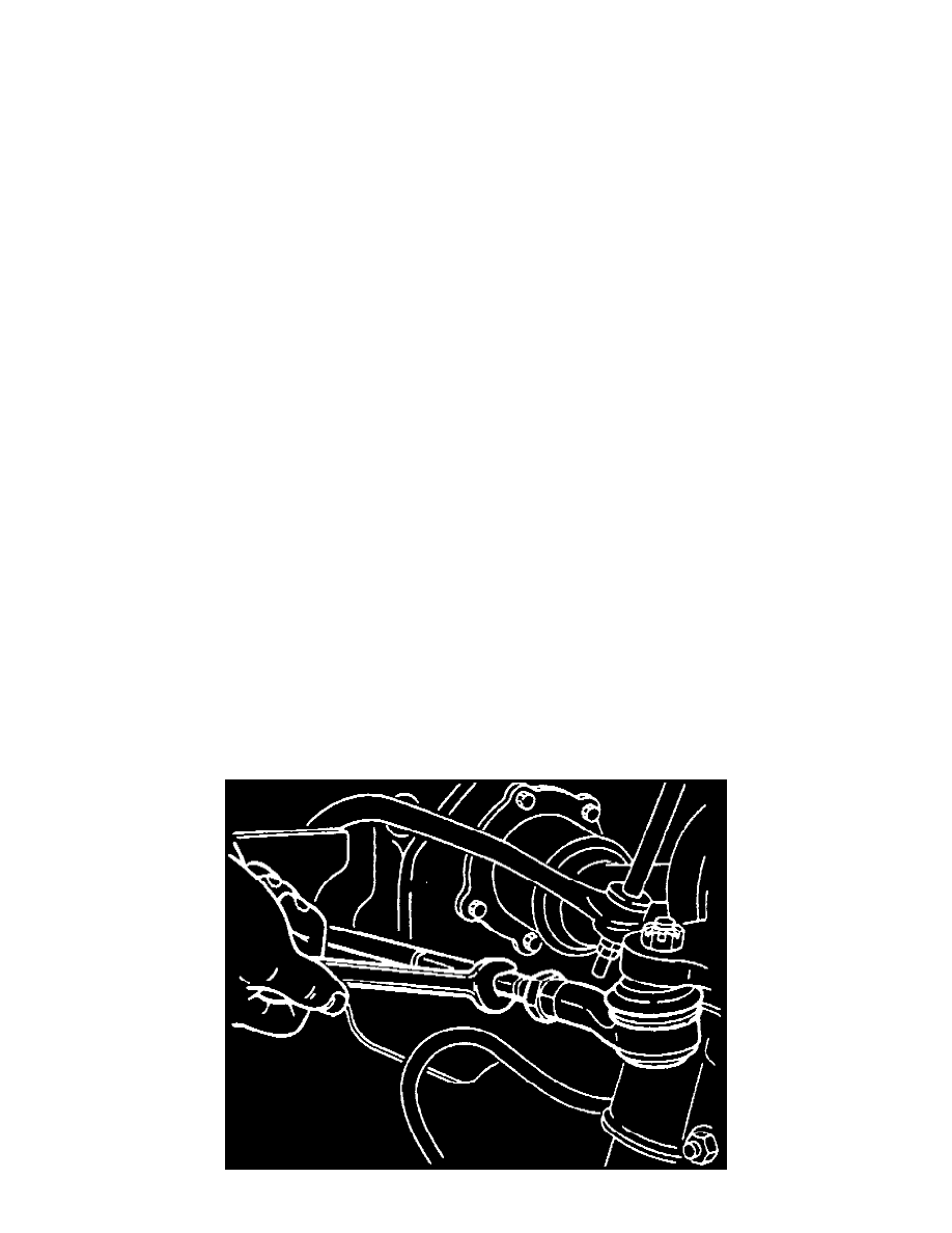
1. Loosen jam nuts at tie rod ends, then release clips at small ends of steering gear boots. Ensure boots are free on tie rod ends so that they will not be
twisted when tie rods are turned.
Pinch or Ctrl + scroll to zoom. Double-tap to reset.
Parts & tools for this job For 1994 Ford Probe 2.5L
- TOOLTie rod end toolSearch: tie rod end puller
- TOOLBall joint separatorSearch: ball joint separator
- FLUIDPower steering fluidSearch: Ford power steering fluid
Links open Amazon search results in a new tab. As an Amazon Associate I earn from qualifying purchases.