ford Workshop Repair Guides

Ford Workshop Service and Repair Manuals

Diagnosis and Testing|Removal and Installation > < Steering Column Switches
Steering Column Switches - Steering Column Switches Puma 1998 (06/1997-12/2001)
Diagnosis and Testing

Inspection and Verification

  1. Verify the customer concern.
  1. Visually inspect for obvious signs of damage. Refer to the following chart:

Visual Inspection Chart

Mechanical Electrical
  • Ignition switch.
  • Battery.
  • Fuse.
  • Wiring.
  • Connector(s).
  1. If inspection reveals an obvious cause, rectify this before continuing. If the concern remains, proceed to the Symptom Chart.
  1. Additional information on connectors is available. Refer to the relevant wiring diagram.

Symptom Chart

Symptom Chart

Symptom Possible Sources Action
The ignition switch is inoperative
*
Switch.
*
Circuit.
*
Fuse.
*
GO to Pinpoint Test A.
No power in ACC
*
Switch.
*
Circuit.
*
GO to Pinpoint Test B.
No power in RUN
*
Switch.
*
Circuit.
*
Relay.
*
GO to Pinpoint Test C.
No power in START
*
Switch.
*
Circuit(s).
*
Relay.
*
GO to Pinpoint Test D.
The multifunction switch hazard warning switch does not operate correctly
*
Fuse(s).
*
Circuit.
*
Switch.
*
GO to Pinpoint Test E.

Pinpoint Tests

PINPOINT TEST A : THE IGNITION SWITCH IS INOPERATIVE

TEST CONDITIONS DETAILS/RESULTS/ACTIONS
A1: CHECK THE IGNITION SWITCH CONNECTOR
1
Remove the steering column shrouds and check the ignition switch connector.

Is the ignition switch connector clean and secure?
Yes
No
CLEAN and SECURE the ignition switch connector as required. TEST the system for normal operation.
A2: CHECK FUSE 40 (60A)
1
CHECK Fuse 40 (60A).
2
Check the fuse 40 (60A).

Is the fuse OK?
Yes
No
INSTALL a new fuse 40 (60A). TEST the system for normal operation. If the fuse fails again GO to A3.
A3: CHECK CIRCUIT 30 (RD) FOR SHORT TO GROUND
1
Disconnect Fuse 40 (60A).

2
Measure the resistance between the fuse 40 connector pin 1, circuit 30 (RD) and ground.

Is the resistance greater than 10,000 ohms?
Yes
No
REPAIR circuit 30 (RD). TEST the system for normal operation.
A4: CHECK FOR OPEN ON CIRCUIT 30 (RD)
1
Disconnect Fuse 40 (60A).
2
Disconnect Ignition switch connector C61.

3
Measure the resistance between the ignition switch connector C61 pin 4, circuit 30 (RD) and fuse 40 connector pin 1, circuit 30 (RD).

Is the resistance less than 5 ohms?
Yes
No
REPAIR circuit 30 (RD). TEST the system for normal operation
A5: CHECK THE IGNITION SWITCH
1
Carry out the ignition switch component test as described in this section.

Does the ignition switch test OK?
Yes
VERIFY the customer concern.
No
INSTALL a new ignition switch. TEST the system for normal operation.

PINPOINT TEST B : NO POWER IN ACC

TEST CONDITIONS DETAILS/RESULTS/ACTIONS
B1: CHECK FOR OPEN /SHORT TO GROUND ON CIRCUIT 75 (YE)
1
Disconnect Ignition switch connector C61.
2
Disconnect Fuse 19 (10A).

3
Measure the resistance between the ignition switch connector C61 pin 1, circuit 75 (YE) and ground, and between the ignition switch connector C61 pin 1, circuit 75 (YE) and the fuse 19 (10A).

Is the resistance between connector C61 pin 1, circuit 75 (YE) and ground greater than 10,000 ohms, and is the resistance between connector C61 pin 1, circuit 75 (YE) and the fuse 19 (10A) less than 5 ohms?
Yes
INSTALL a new ignition switch. TEST the system for normal operation.
No
REPAIR circuit 75 (YE). TEST the system for normal operation.

PINPOINT TEST C : NO POWER IN RUN

TEST CONDITIONS DETAILS/RESULTS/ACTIONS
C1: CHECK FUSE 38 (60A)
1
CHECK .
2
Check the fuse 38 (60A).

Is the fuse OK?
Yes
No
INSTALL a new fuse 38 (60A). TEST the system for normal operation. If the fuse fails again GO to C2.
C2: CHECK FOR SHORT TO GROUND ON CIRCUIT 30 (RD)
1
Disconnect Fuse 38 (60A).
2
Disconnect Ignition relay C47.

3
Measure the resistance between the fuse 38 connector pin 1, circuit 30 (RD) and ground.

Is the resistance greater than 10,000 ohms?
Yes
No
REPAIR circuit 30 (RD). TEST the system for normal operation.
C3: CHECK THE IGNITION SWITCH
1
Carry out the ignition switch component test. Refer to the procedure in this section.

Does the ignition switch test OK?
Yes
No
INSTALL a new ignition switch. TEST the system for normal operation.
C4: CHECK FOR OPEN ON CIRCUITS 15 (GN) AND 15 (GN/BU)
1
Ignition switch in position II.

2
Measure the voltage between ignition relay C47 pin 1, circuit 15 (GN) and 15 (GN/BU) and ground

Is the voltage greater than 10 volts?
Yes
No
Repair circuit 15 (GN) or 15 (GN/BU). TEST the system for normal operation.
C5: CHECK THE IGNITION RELAY GROUND
1
Disconnect Interior light relay.
2
Ignition switch in position 0.

3
Measure the resistance between the ignition relay C47 pin 2, circuit 31 (BK) and ground.

Is the resistance less than 5 ohms?
Yes
No
Repair circuit 31 (BK). TEST the system for normal operation.
C6: CHECK THE IGNITION RELAY POWER FEED
1
Connect Interior light relay.

2
Measure the voltage between the ignition relay C47 pin 3, circuit 30 (RD) and ground.

Is the voltage greater than 10 volts?
Yes
No
REPAIR circuit 30 (RD). TEST the system for normal operation.
C7: CHECK FOR OPEN ON CIRCUIT 15 (GN)
1
Disconnect Fuse 17 (15A).

2
Measure the resistance between ignition relay C47 pin 5, circuit 15 (GN) and supply side of Fuse F17 (15A).

Is the resistance less than 5 ohms?
Yes
INSTALL a new ignition relay. TEST the system for normal operation.
No
REPAIR circuit 15 (GN). TEST the system for normal operation.

PINPOINT TEST D : NO POWER IN START

TEST CONDITIONS DETAILS/RESULTS/ACTIONS
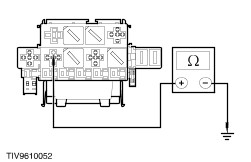
D1: CHECK FUSE 36 (60A)
1
CHECK Fuse 36 (60A).
2
Check the fuse 36 (60A).

Is the fuse OK?
Yes
No
INSTALL a new fuse 36 (60A). TEST the system for normal operation. If the fuse fails again GO to D2.
D2: CHECK FOR SHORT TO GROUND ON CIRCUIT 30 (RD)
1
Disconnect Fuse 36 (60A).

2
Measure the resistance between the fuse 36 (60A) connector pin 1, circuit 30 (RD) and ground.

Is the resistance greater than 10,000 ohms?
Yes
No
REPAIR circuit 30 (RD). TEST the system for normal operation.
D3: CHECK THE IGNITION SWITCH
1
Carry out the ignition switch component test. Refer to the procedure in this section.

Does the ignition switch test OK?
Yes
No
INSTALL a new ignition switch. TEST the system for normal operation.
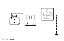
D4: CHECK FOR SHORT/OPEN ON CIRCUIT 50 (GY)
1
Disconnect Start inhibit relay C163.
2
Disconnect Ignition switch C61.

3
Measure the resistance between the ignition switch connector C61 pin 3, circuit 50 (GY) and ground, and between the ignition switch connector C61 pin 3, circuit 50 (GY) and the start inhibitor relay connector C163 pin 2, circuit 50 (GY).

Is the resistance between connector C61 pin 3, circuit 50 (GY) and ground greater than 10,000 ohms, and is the resistance between connector C61 pin 3, circuit 50 (GY) and pin 2, circuit 50 (GY) less than 5 ohms?
Yes
No
REPAIR circuit 50 (GY). TEST the system for normal operation.
D5: CHECK THE START INHIBIT RELAY GROUND

1
Measure the resistance between the start inhibit relay connector C163 pin 1, circuit 315 (BK/RD) and ground.

Is the resistance between 45 and 50 ohms?
Yes
No
REPAIR circuit 315 (BK/RD). TEST the system for normal operation.
D6: CHECK THE START INHIBIT RELAY POWER FEED

1
Measure the voltage between the start inhibit relay connector C163 pin 5, circuit 30 (RD) and ground.

Is the voltage greater than 10 volts?
Yes
No
REPAIR circuit 30 (RD). TEST the system for normal operation.
D7: CHECK FOR OPEN ON CIRCUIT 50 (GY/BK)
1
Disconnect Connector C188.

2
Measure the resistance between start inhibit relay connector C163 pin 5, circuit 50 (GY/BK) and connector C188 pin 1, circuit 50 (GY/BK).

Is the resistance less than 5 ohms?
Yes
INSTALL a new start inhibit relay. TEST the system for normal operation.
No
REPAIR circuit 50 (GY/BK) TEST the system for normal operation.

PINPOINT TEST E : THE MULTIFUNCTION SWITCH/HAZARD WARNING SWITCH DOES NOT OPERATE CORRECTLY

TEST CONDITIONS DETAILS/RESULTS/ACTIONS
E1: CHECK THE EXTERIOR LIGHTING
1
Operate the exterior lights.

Do the exterior lights work OK?
Yes
No
REFER to Section  417-01 Exterior Lighting. to diagnose the exterior lighting.
E2: CHECK THE WIPER AND WASHER
1
Operate the wipers and washers.

Do the wipers and washers work OK?
Yes
VERIFY the customer concern.
No
REFER to Section  501-16 Wipers and Washers. to diagnose the wipers and washers.

Diagnosis and Testing|Removal and Installation > < Steering Column Switches