| General Procedures Special Tool(s) | | Pliers, valve adjusting shims 303-196 (21-107) | | | Pliers, spark plug connector 303-226 (21-226) | Materials Name Specification Silicone grease ESE-M1C171-AA Adjustment | | -
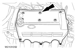
Remove the cover plate from the cylinder head cover. | | | -
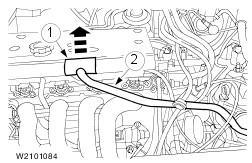
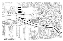
Pull off the positive crankcase ventilation hose. - Open the wiring harness cover.
- Disconnect the hose.
| | | -
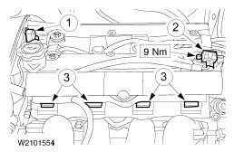
CAUTION:Pull off the spark plug connectors in line with the spark plugs (for angled spark plug connectors use Special Tool 303-622). CAUTION:Do not pull the cable when removing the spark plug connector. If necessary, Remove the ignition cables from the ignition coil to avoid kinking the cables. Turn the spark plug connector slightly before removing to loosen the seal. Separate the connectors. - Variable camshaft timing (VCT) solenoid valve
- Disconnect the plug and remove the camshaft position sensor (CMP sensor).
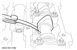
- Carefully take out the rubber seal.
- Unclip the injector rail, disconnect it and lay it to one side.
- Pull off the spark plug connectors.
- Unclip the ignition cables.
| | | -
Remove the cylinder head cover. | | | -
Check the valve clearance on all valves and make a note of the measurements. - Specified valve clearance (engine cold), intake valves 0,15 mm - 0,25 mm.
- Specified valve clearance (engine cold), exhaust side 0,25 mm - 0,35 mm.
| | | -
NOTE:Keep the bucket tappets and adjustment shims together in order. Remove the bucket tappets and their adjustment shims. | | | -
Choose a new adjustment shim. - Thickness of new adjustment shim = measured valve clearance + thickness of adjustment shim removed = average valve clearance (required value).
- The selected thickness must not vary from the calculated thickness by more than 0.03 mm.
| | | -
Install the bucket tappets with new adjustment shims. | | | -
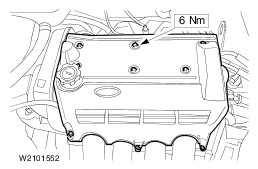
Fit the cylinder head cover. | | | -
CAUTION:Use a blunt object (e.g. a plastic cable tie) to apply the silicone grease, to avoid damaging the spark plug connector seal. CAUTION:Slide on the spark plug connector keeping it in line with the spark plug. NOTE:Grease the inside of the spark plug connectors. Join the connectors. - VCT solenoid valve.
- Install the CMP sensor and connect the plug.
- Push on the injector rail.
- Coat the inside of the spark plug connectors to a depth of 5-10 mm with silicone grease .
- Push on the spark plug connectors.
- Clip the ignition cables in place.
| | | -
Push on the positive crankcase ventilation hose. - Push on the hose.
- Close the wiring harness cover.
| | | -
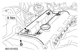
NOTE:First fit all bolts loosely, then align the cover and tighten them to the specified torque. Fit the cover plate onto the cylinder head cover. | | |