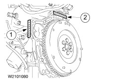
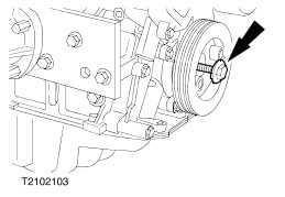
Crank gear
NOTE:Do not dismantle the crank gear.
The bearing clearances and bearing shells have very fine tolerances, as a result of which the crank gear components cannot be renewed individually. It is not possible to measure the main bearing clearance using conventional methods.
The crankshaft has eight counterbalances and runs on five bearings.
The lower crankcase provides significant additional strength for the cylinder block.
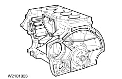
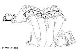
Cylinder head
The cylinder head is made of an aluminium-silicium alloy and is accurately positioned on the cylinder block by means of two guide sleeves.
In service the cylinder head is supplied complete with fitted valves and bearing caps. The studs must be renewed.
The cylinder head has four valves per cylinder. The valve angle is slightly asymmetrical. The exhaust valves are inclined at 2 degrees more than the intake valves.
The intake camshaft is equipped with variable camshaft timing.
The spark plugs are slightly offset from the middle of the combustion chamber to permit use of the largest possible intake valves.
The valve guides and valve seats are made from sintered metal.
An additional coolant duct is located between the exhaust valve guides to provide extra cooling for the exhaust valve seats.
5
-
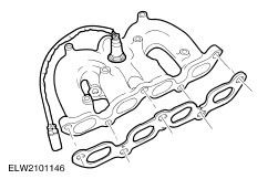
Solenoid valve of VCT adjustment unit
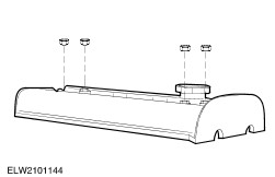
Cylinder head cover
NOTE:Remove the camshaft position sensor (CMP sensor) before removing the cylinder head cover.
The cylinder head cover is made of magnesium, and the cylinder head gasket can be renewed separately.
NOTE:The cylinder head cover gasket does not need to be renewed every time it is taken off. Check it visually and only fit a new gasket if it is damaged.
The cylinder head cover is attached to four studs on the camshaft bearing caps. These studs are sealed with four rubber bungs with torque limiters. In the event of leaks these four rubber bungs can be renewed separately.
If a new or different cylinder head cover is fitted then renew the four rubber bungs and the seal for the VCT adjustment unit solenoid valve.
New cylinder head covers are supplied with a gasket and four new bungs.
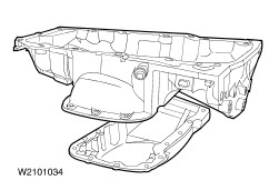
Oil pan
The oil pan has been enlarged to cope with the additional oil requirements compared to the 1,25 and 1,4 litre Zetec-SE engines.
For manufacturing reasons the oil pan consists of two parts.
CAUTION:Do not use any sharp tools to remove the oil pan.
NOTE:During removal always take off the lower part of the oil pan first, as this makes two of the bolts on the upper part accessible.
Both parts of the oil pan are sealed using sealant WSE-M4G323-A4.
NOTE:Two bolts inside the upper part of the oil pan need additional steel sealing rings.
NOTE:Align the oil pan to the cylinder block using a straightedge.
5
-
Oil scraper ring (bottom)
NOTE:TOP marking on plain compression ring and Napier ring.
The piston rings can be renewed separately.
Each ring gap is 90 degrees offset from the next. This also applies to the three elements of the oil scraper ring.
The dots on the piston crown point towards the timing belt end.
There are no oversize pistons available.
The pistons cannot be renewed separately.
As a result of the variable camshaft timing it has become necessary to introduce notches in the piston crown.
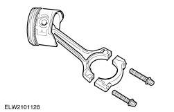
Connecting rods
The connecting rods are made of forged steel.
The big-ends are separated by fracture. This process produces a perfect fit for the big-end bearing caps.
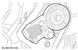
Valve train
Two overhead camshafts are driven by the crankshaft via a timing belt. They control the valves via tappets and adjustment shims.
The valve clearance should be checked every 150,000 km.
The timing belt should be renewed after 150,000 km or 10 years.
The tappets are mechanical bucket tappets.
The valve adjustment shims are located underneath the bucket tappets.
This arrangement has the following advantages:
- smaller and therefore lighter adjustment shims.
- the weight of the moving parts in the valve train is reduced.
- the valve train is more stable at high engine speeds.
The valve stems are nitration-hardened and the valve seats are reinforced.
The exhaust valves are made of two different materials (two different alloys for the valve stems and the valve heads).
Camshafts
Check the camshaft bearings whenever the camshafts are renewed. In the event of damage renew the cylinder head and the camshaft bearing caps.
Both camshafts have a cast hexagon (21 mm) which is used for turning them.
Both camshafts have a slot at the clutch end to take the TDC setting tool.
CAUTION:Lubricate the camshafts with engine oil before installing them.
CAUTION:Tighten the camshaft bearing caps in two stages following the tightening sequence.
The numbering of the bearing caps starts at the timing belt end, with nos. 1 to 5 on the exhaust side and 6 to 0 on the intake side.
NOTE:The camshaft timing belt pulleys are free to turn on the camshafts once the central bolts have been undone.
The VCT adjustment unit is bolted to the intake camshaft. The hollow bolt used for this purpose also forms part of the oil circuit of the VCT adjustment unit.
Besides the usual reference wheel for detecting the first cylinder position, there are four more cams on its circumference, at 90 degrees to each other, used by the camshaft timing unit to exactly determine the position of the camshaft.
NOTE:Always renew the hollow bolt after removal.
Variable camshaft timing (VCT)
The camshaft adjustment is map-controlled, but also responds to mass air flow, intake air temperature and coolant temperature via the PCM.
The solenoid valve is supplied with voltage pulses from the PCM that determine the required current.
NOTE:If the PCM detects a fault in the VCT system it no longer supplies the solenoid valve with a voltage, and the VCT adjustment unit returns to its original position. This prevents any adjustment.
1
-
Inner helical gear (connected to the camshaft)
2
-
Adjustment piston with inner and outer helical gear
3
-
Outer helical gear (connected to the camshaft timing pulley)
5
-
VCT adjustment unit solenoid valve
The adjustment of the camshaft is performed by a piston that moves along the axis of the camshaft.
This adjustment piston has an inner and outer helical gear.
The helical gears that engage in the adjustment piston are connected to the camshaft timing pulley (outer gear) on the one hand and the camshaft (inner gear) on the other.
Depending on the required setting of the camshaft, pressurised engine oil is delivered either to the front or the back of the piston to move it backwards or forwards along the camshaft axis.
The helical gears translate this axial movement into a rotation of the camshaft in relation to the camshaft timing pulley.
The build height of the adjustment unit was reduced by using two pairs of helical gears.
Adjustment angle of the intake camshaft
1
-
Adjustment angle of the adjustment piston relative to the camshaft timing pulley
2
-
Adjustment angle of the camshaft relative to the adjustment piston
3
-
Camshaft timing belt pulley
The camshaft timing pulley is directly linked to the crankshaft via the timing belt and is therefore not rotated in relation to the crankshaft during adjustment.
When the applied engine oil pressure forces the adjustment piston to move axially, the helical gears produce the following rotations:
- Rotation of the adjustment piston relative to the camshaft timing pulley via the outer helical gear.
- Rotation of the camshaft relative to the adjustment piston via the inner helical gear.
- These two rotations add up to give the overall adjustment angle of the camshaft.
In this way the camshaft can be adjusted by up to 20 degrees compared to the camshaft timing pulley.
The adjustment angle depends on the operating conditions of the engine.
Oil circuit of the VCT adjustment unit
Advancing the camshaft
Oil is supplied via the solenoid valve, through the oil supply slots on the camshaft and the hollow bolt into chamber 1, which then becomes pressurised.
The adjustment piston is moved axially on the helical gears.
The camshaft timing is advanced.
As a result of the axial movement of the adjustment piston, the oil in chamber 2 is displaced through the gaps in the gears.
The oil can then flow back through the oil supply slots on the camshaft and the return bore in the control piston solenoid valve to the cylinder head.
Retarding the camshaft
Oil is supplied via the solenoid valve, through the oil supply slots on the camshaft and the hollow bolt into chamber 2, which then becomes pressurised.
The adjustment piston is moved axially on the helical gears.
The camshaft timing is retarded.
As a result of the axial movement of the adjustment piston, the oil in chamber 1 is displaced through the gaps in the gears.
The oil can then flow back through the oil supply slots on the camshaft and the return bore in the control piston solenoid valve to the cylinder head.