| Diagnosis and Testing Inspection and Verification - Verify the customer concern.
- Visually inspect for obvious signs of damage. Refer to the following chart:
Visual Inspection Chart | Mechanical | Electrical | - Window regulator.
- Window glass.
- Window channel.
| - Fuse.
- Circuit.
- Connections.
- Motor.
| - If inspection reveals an obvious cause, rectify this before continuing. If the concern remains, proceed to the Symptom Chart.
- Additional information on connectors is available. Refer to the relevant wiring diagram.
Symptom Chart Symptom Chart | Symptom | Possible Sources | Action | | All door windows inoperative | * Fuse. * Circuit(s). * Driver door window switch. | * GO to Pinpoint Test A | | Driver door window inoperative | * Circuit(s). * Driver door window switch. * Driver door window motor. | * GO to Pinpoint Test B | | Passenger door window inoperative | * Circuit(s). * Driver door window switch. * Passenger door window switch. * Passenger door window motor. | * GO to Pinpoint Test C | | The rear window will not demist | * Circuit(s). * Heated rear window switch. * Relay. * Fuse. | * GO to Pinpoint Test D | Pinpoint Tests | PINPOINT TEST A : ALL DOOR WINDOWS INOPERATIVE | | TEST CONDITIONS | DETAILS/RESULTS/ACTIONS | | A1: CHECK FUSE 11 (30A) | | | 1 CHECK Fuse 11 (30A). | | | Is the fuse OK? Yes No INSTALL a new Fuse 11 (30A). TEST system for normal operation. If the fuse fails again, GO to A2. GO to Pinpoint Test A. | | A2: CHECK FOR SHORT TO GROUND ON CIRCUIT 14 (VT/BU) | | | 1 Disconnect Fuse 11 (30A). | | | 2 Measure the resistance between fuse 11 connector pin 1, circuit 14 (VT/BU) and ground. | | | Is the resistance greater than 10,000 ohms? Yes No REPAIR circuit 14 (VT/BU). TEST the system for normal operation. | | A3: CHECK FOR CONTINUITY ON CIRCUIT 14 (VT/BU) 29-AJ7 (OG/BU) | | | 1 Disconnect Driver window switch C142a. | | | 2 Measure the resistance between fuse 11 connector pin 1, circuit 14 (VT/BU) and the driver window switch C142a-2, circuit 14 (VT/BU)/29-AJ7 (OG/BU). | | | Is the resistance less than 5 ohms? Yes No REPAIR circuit 14 (VT/BU) 29-AJ7 (OG/BU). TEST the system for normal operation. | | A4: CHECK FOR CONTINUITY ON CIRCUIT 31-AJ7 (BK) | | | 1 Measure the resistance between the driver window switch C142a-3, circuit 31-AJ7 (BK) and ground. | | | Is the resistance less than 5 ohms? Yes INSTALL a new driver power window switch. TEST the system for normal operation. No REPAIR circuit 31-AJ7 (BK). TEST the system for normal operation. | | PINPOINT TEST B : DRIVERS DOOR WINDOW INOPERATIVE | | TEST CONDITIONS | DETAILS/RESULTS/ACTIONS | | B1: CHECK THE DRIVER WINDOW SWITCH | | | 1 Disconnect Driver window switch C142a. | | | 2 Ignition switch in position II. | | | 3 Connect a jumper wire between the driver window switch C142a-1, circuit 32-AJ26 (WH) and pin 3, circuit 31-AJ7 (BK) and between pin 2, circuit 29-AG7 (OG/BU) and pin 7, circuit 33-AJ26 (YE). | | | Does the driver door window go down? Yes INSTALL a new driver door window switch. TEST the system for normal operation. No | | B2: CHECK FOR CONTINUITY ON CIRCUIT 31-AJ7 (BK) | | | 1 Measure the resistance between the driver window switch C142a-3, circuit 31-AJ7 (BK) and ground. | | | Is the resistance less than 5 ohms? Yes No REPAIR circuit 31-AJ7 (BK). TEST the system for normal operation. | | B3: CHECK CIRCUIT 33-AJ26 (YE) | | | 1 Disconnect Driver window motor C141. | | | 2 Measure the resistance between the driver window switch C142a-7, circuit 33-AJ26 (YE) and the driver door window motor C141-1, and between the driver door window switch C142a-7, circuit 33-AJ26 (YE) and ground? | | | Is the resistance less than 5 ohms between the switch connector and motor connector and greater than 10,000 ohms between the switch connector and ground? Yes No REPAIR circuit 33-AJ26 (YE). TEST the system for normal operation. | | B4: CHECK CIRCUIT 32-AJ26 (WH) | | | 1 Measure the resistance between the driver window switch C142a-1, circuit 32-AJ26 (WH) and the driver door window motor C141-2, and between the driver window switch C142a-1, circuit 32-AJ26 (WH) and ground. | | | Is the resistance less than 5 ohms between the switch connector and motor connector and greater than 10,000 ohms between the switch connector and ground? Yes INSTALL a new driver window motor. TEST the system for normal operation. No REPAIR circuit 32-AJ26 (WH). TEST the system for normal operation. | | PINPOINT TEST C : PASSENGER DOOR WINDOW INOPERATIVE | | TEST CONDITIONS | DETAILS/RESULTS/ACTIONS | | C1: CHECK THE DRIVER SWITCH | | | 1 Disconnect Driver passenger window switch C142b. | | | 2 Ignition switch in position II. | | | 3 Connect a jumper wire between the driver door passenger window switch C142b-1, circuit 32-AJ18 (WH/VT) and pin 3, circuit 31-AJ7 (BK), and between pin 2, circuit 29-AJ9 (OG/BK) and pin 7, circuit 33-AJ18 (YE/VT). | | | Does the front passenger door window operate? Yes INSTALL a new driver door window switch. TEST the system for normal operation. No | | C2: CHECK CIRCUIT 29-AJ9 (OG/BK) | | | 1 Ignition switch in position 0. | | | 2 Disconnect Driver window switch C142a. | | | 3 Measure the resistance between the driver door switch C142a-2, circuit 29-AJ9 (OG/BK) and the driver door passenger window switch C142b-2, circuit 29-AJ9 (OG/BK). | | | Is the resistance less than 5 ohms? Yes No REPAIR circuit 29-AJ9 (OG/BK). TEST the system for normal operation. | | C3: CHECK CIRCUIT 31-AJ7 (BK) | | | 1 Measure the resistance between the driver door passenger window switch C142a-3, circuit 31-AJ7 (BK) and ground. | | | Is the resistance less than 5 ohms? Yes No REPAIR circuit 31-AJ7 (BK). TEST the system for normal operation. | | C4: CHECK CIRCUIT 32-AJ18 (WH/VT) | | | 1 Disconnect Passenger window switch C137. | | | 2 Measure the resistance between the passenger window switch C137-6, circuit 32-AJ18 (WH/VT) and the driver door passenger window switch C142b, circuit 32-AJ18 (WH/VT) and between the passenger window switch C137-6, circuit 32-AJ18 (WH/VT) and ground. | | | Is the resistance less than 5 ohms between pin 6 and pin 1, and greater than 10,000 ohms between pin 6 and ground? Yes No REPAIR circuit 32-AJ18 (WH/VT). TEST the system for normal operation. | | C5: CHECK CIRCUIT 33-AJ18 (YE/VT) | | | 1 Measure the resistance between the passenger window switch C137-3, circuit 33-AJ18 (YE/VT) and the driver door passenger window switch C142-7, circuit 33-AJ18 (YE/VT) and between the passenger window switch C137-3, circuit 33-AJ18 (YE/VT) and ground. | | | Is resistance less than 5 ohms between pin 3 and pin 7, and greater than 10,000 ohms between pin 3 and ground? Yes No REPAIR circuit 33-AJ18 (YE/VT). TEST the system for normal operation. | | C6: CHECK CIRCUIT 14-AJ18 (VT/WH) | | | 1 Ignition switch in position II. | | | 2 Measure the voltage between the passenger window switch C137-2, circuit 14-AJ18 (VT/WH) and ground. | | | Is the voltage greater than 10 volts? Yes No REPAIR circuit 14-AJ18 (VT/WH). TEST the system for normal operation. | | C7: CHECK THE PASSENGER WINDOW SWITCH | | | 1 Connect Drivers Switch. | | | 2 Connect a jumper wire between the passenger window switch C137-6, circuit 32-AJ27 (WH/VT) and pin 1 circuit 32-AJ27 (WH/VT), and between pin 7, circuit 33-AJ27 (YE/VT) and pin 2, 29-AJ18 (OG/WH). | | | Does the front passenger power window go down? Yes No INSTALL a new passenger window switch. TEST the system for normal operation. | | C8: CHECK CIRCUIT 32-AJ27 (WH/VT) | | | 1 Ignition switch in position 0. | | | 2 Disconnect Passenger door window motor C136. | | | 3 Measure the resistance between the passenger window switch C137-1, circuit 32-AJ27 (WH/VT) and the passenger door window motor C136-2, and between the passenger window switch C137-1, circuit 32-AJ27 (WH/VT) and ground. | | | Is the resistance less than 5 ohms between pin 1 and pin 2, and greater than 10,000 ohms between pin 1 and ground? Yes No REPAIR circuit 32-AJ27 (WH/VT). TEST the system for normal operation. | | C9: CHECK CIRCUIT 33-AJ27 (YE/VT) | | | 1 Measure the resistance between the passenger window switch C137-7, circuit 33-AJ27 (YE/VT) and the passenger door window motor C136-1, and between the passenger window switch C137-7, circuit 33-AJ27 (YE/VT) and ground. | | | Is the resistance less than 5 ohms between pin 7 and pin 1, and greater than 10,000 ohms between pin 7 and ground? Yes INSTALL a new front passenger window motor. TEST the system for normal operation. No REPAIR circuit 33-AJ27 (YE/VT). TEST the system for normal operation. | | PINPOINT TEST D : THE REAR WINDOW WILL NOT DEFROST | | TEST CONDITIONS | DETAILS/RESULTS/ACTIONS | | D1: CHECK FUSE 13 (15A) | | | 1 CHECK Fuse 13 (15A). | | | Is the fuse OK? Yes No INSTALL a new fuse 13 (15A). TEST the system for normal operation. If the fuse fails again, GO to D2. | | D2: CHECK FOR SHORT TO GROUND CIRCUIT 14-HB22 (VT/BK) | | | 1 Disconnect Fuse 13 (15A). | | | 2 Disconnect Heated rear window switch. | | | 3 Measure the resistance between fuse 13 connector pin 1, circuit 14-HB22 (VT/BK) and ground. | | | Is the resistance greater than 10,000 ohms? Yes No REPAIR circuit 14-HB22 (VT/BK). TEST the system for normal operation. | | D3: CHECK FUSE 4 (20A) | | | 1 CHECK Fuse 4 (20A). | | | Is the fuse OK? Yes No INSTALL a new fuse 4 (20A). TEST the system for normal operation. If the fuse fails again, GO to D4. | | D4: CHECK FOR SHORT TO GROUND ON CIRCUIT 29-HB21 (OG/GN) | | | 1 Disconnect Fuse 4 (20A). | | | 2 Measure the resistance between fuse 4 connector pin 1, circuit 29-HB21 (OG/GN) and ground. | | | Is the resistance greater than 10,000 ohms? Yes No REPAIR circuit 29-HB21 (OG/GN). TEST the system for normal operation. | | D5: TEST THE REAR WINDOW HEATER RELAY | | | 1 Test the relay. Refer to the Component Tests in this section. | | | Did the relay test OK? Yes No INSTALL a new relay. TEST the system for normal operation. | | D6: TEST THE REAR WINDOW HEATER SWITCH | | | 1 Test the switch. Refer to the Component Tests in this section. | | | Did the switch test OK? Yes No INSTALL a new switch. TEST the system for normal operation. | | D7: CHECK CIRCUIT 14 (VT/BK) | | | 1 Ignition switch in position II. | | | 2 Measure the voltage between the rear window heater switch connector pin 1, circuit 14 (VT/BK) and ground. | | | Is the voltage greater than 10 volts? Yes No REPAIR circuit 14 (VT/BK). TEST the system for normal operation. | | D8: CHECK CIRCUIT 31 (BK) | | | 1 Ignition switch in position 0. | | | 2 Measure the resistance between the rear window heater switch connector pin 4, circuit 31 (BK) and ground. | | | Is the resistance less than 5 ohms? Yes No REPAIR circuit 31 (BK). TEST the system for normal operation. | | D9: CHECK CIRCUIT 14S (VT/BK) | | | 1 Disconnect Relay. | | | 2 Measure the resistance between the rear window heater switch connector pin 2, circuit 14S (VT/BK) and the heated rear window relay connector pin 2, circuit 14S (VT/BK) and between the heated rear window switch connector pin 2, circuit 14S (VT/BK) and ground. | | | Is the resistance less than 5 ohms between pin 2 and pin 2 and greater than 10,000 ohms between pin 2 and ground? Yes No REPAIR circuit 14S (VT/BK). TEST the system for normal operation. | | D10: CHECK THE GROUND TO THE REAR WINDOW HEATER RELAY | | | 1 Measure the resistance between the rear window relay connector pin 2 circuit 31 (BK) and ground. | | | Is the resistance less than 5 ohms? Yes No REPAIR circuit 31 (BK). TEST the system for normal operation. | | D11: CHECK THE POWER TO THE REAR WINDOW HEATER RELAY | | | 1 Measure the voltage between the rear window heater relay connector pin 3, circuit 29 (OG/GN) and ground. | | | Is the voltage greater than 10 volts? Yes No REPAIR circuit 29 (OG/GN). TEST the system for normal operation. | | D12: CHECK CIRCUIT 14 (VT/BK) | | | 1 Measure the resistance between the rear window heater relay connector pin 5, circuit 14S (VT/BK) and the liftgate contact plate connector plate 2, circuit 14S (VT/BK) and between the heated rear window relay connector pin 5, circuit 14S (VT/BK) and ground. | | | Is the resistance less than 5 ohms between pin 5 and contact plate 2, and greater than 10,000 ohms between pin 5 and ground? Yes No REPAIR circuit 14S (VT/BK). TEST the system for normal operation. | | D13: CHECK CIRCUIT 14S (VT/BU) | | | 1 Disconnect Rear window heater. | | | 2 Measure the resistance between the contact plate connector pin 2, circuit 14S (VT/BU) and the heated rear window connector, circuit 14S (VT/BU) and between the contact plate connector pin 2, circuit 14S (VT/BU) and ground. | | | Is the resistance less than 5 ohms between the contact plate connector pin 2 and the rear window heater power connector, and greater than 10,000 ohms between the contact plate connector pin 2 and ground? Yes No REPAIR circuit 14S (VT/BU). TEST the system for normal operation. | | D14: CHECK THE GROUND TO THE REAR WINDOW HEATER | | | 1 Measure the resistance between the rear window heater ground connector, circuit 31 (BK) and ground. | | | Is the resistance less than 5 ohms? Yes INSTALL a new heated rear window. TEST the system for normal operation. No REPAIR circuit 31 (BK). TEST the system for normal operation. | Component Tests Heated Rear Window Switch - Remove the heated rear window switch.
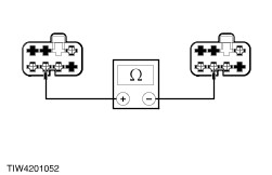
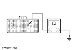
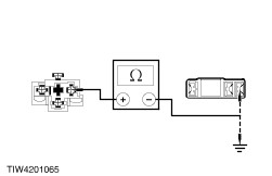
- Measure the resistance between pins 1 and 2 of the switch while operating the switch.
- The resistance should be less than 5 ohms when the switch is in the ON position and greater than 10,000 ohms when in the OFF position.
- If the resistances are not as specified, INSTALL a new heated rear window switch.
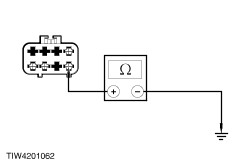
Rear Window Heater Relay - Remove the heated rear window relay.
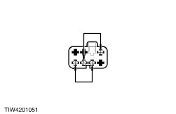
- Using a jumper wire, connect one end to terminal 1 of the relay. Connect the other end to ground.
- Using a second jumper wire, connect one end to terminal 2 of the relay.
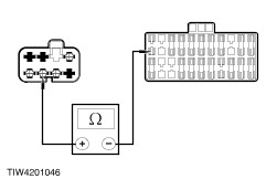
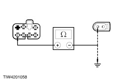
- Connect one lead of an ohmmeter to terminal 3 of the relay. Connect second lead to terminal 5 of the relay. Observe the resistance.
- Momentarily tap the unconnected end of the second jumper wire to the battery power. An audible click should be heard and the resistance on the ohmmeter should drop to zero.
- If the relay does not click and the resistance does not drop to zero, INSTALL a new relay.
Heated Rear Window Grid Wire Test - Using a bright lamp inside the vehicle, visually inspect the wire grid from the outside. A broken grid conductor will appear as a brown spot.
- Start the engine and set the heated rear window switch to ON, the indicator light should illuminate.
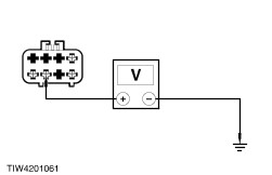
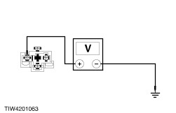
- Work inside the vehicle with a 12 volt DC voltmeter. Contact the broad red-brown strips on the rear window, positive lead to the battery side and the negative lead to ground side. The meter reading should be 10-12 volts. A lower voltage reading indicates a loose heated rear window ground wire connection at the heated rear window ground wire screws.
- Contact a ground point with the negative lead of the meter. The voltage reading should not change.
- With the negative lead of the meter grounded, touch each grid line of the heated rear window at its midpoint with the positive meter lead. A reading of approximately six volts indicates that the line is good. A reading of zero volts indicates that the line is broken between the midpoint and the B+ side of the grid line. A reading of 12 volts indicates that the circuit is broken between the midpoint of the grid line and ground.
- Install a new heated rear window using the procedures as described under the general procedures if necessary.
| |