| Diagnosis and Testing Special Tool(s) | | Alignment Pins, Subframe 205-316 (15-097A) | General Equipment Ford approved diagnostic tool Inspection and Verification - Verify the customer concern.
- Visually inspect for obvious signs of mechanical damage.
Visual Inspection Chart | Mechanical | Electrical | - Tire pressure(s)
- Wheels and tires
- Wheel knuckles
- Tie-rod ends
- Front suspension lower arm ball joints
- Front suspension lower arm bushings
- Front strut and spring assemblies
- Front and rear stabilizer bars and connecting links
- Rear springs
- Shock absorbers
- Rear suspension lower arms
| - Wiring harness(es).
- Electrical connector(s).
- Switch(es).
- Shock absorber solenoid(s)
- vertical acceleration sensor(s)
- Height sensor(s)
- Adaptive damping module
| - If an obvious cause for an observed or reported concern is found, correct the cause (if possible) before proceeding to the next step.
- Retrieve the Diagnostic Trouble Code (DTC)s and refer to the DTC Index Chart.
DTC Index Chart | DTC | Description/Condition | Possible Source | Action | | C110C11 | Left front shock absorber solenoid circuit - short to ground | Circuit(s) or solenoid | GO to Pinpoint Test D. | | C110C12 | Left front shock absorber solenoid circuit - short to power | Circuit(s) or solenoid | GO to Pinpoint Test E. | | C110C13 | Left front shock absorber solenoid circuit - open circuit | Circuit(s) or solenoid | GO to Pinpoint Test F. | | C110C18 | Left front shock absorber solenoid circuit - current below threshold | Solenoid | Connect the Ford approved diagnostic tool and clear the DTC. Carry out a road test for approximately 15 to 20 km (9 to 12 miles) using various road surfaces and conditions. Using the Ford approved diagnostic tool CHECK for the DTC. If the DTC is present, INSTALL new front shock absorbers.
REFER to: Shock Absorber and Spring Assembly (204-01 Front Suspension, Removal and Installation) /
Shock Absorber and Spring Assembly (204-01 Front Suspension, Disassembly and Assembly).
TEST the system for normal operation. | | C110C19 | Left front shock absorber solenoid circuit - current above threshold | Solenoid | Connect the Ford approved diagnostic tool and clear the DTC. Carry out a road test for approximately 15 to 20 km (9 to 12 miles) using various road surfaces and conditions. Using the Ford approved diagnostic tool CHECK for the DTC. If the DTC is present, INSTALL new front shock absorbers.
REFER to: Shock Absorber and Spring Assembly (204-01 Front Suspension, Removal and Installation) /
Shock Absorber and Spring Assembly (204-01 Front Suspension, Disassembly and Assembly).
TEST the system for normal operation. | | C110C1D | Left front shock absorber solenoid circuit - current out of range | Solenoid | Connect the Ford approved diagnostic tool and clear the DTC. Carry out a road test for approximately 15 to 20 km (9 to 12 miles) using various road surfaces and conditions. Using the Ford approved diagnostic tool CHECK for the DTC. If the DTC is present, INSTALL new front shock absorbers.
REFER to: Shock Absorber and Spring Assembly (204-01 Front Suspension, Removal and Installation) /
Shock Absorber and Spring Assembly (204-01 Front Suspension, Disassembly and Assembly).
TEST the system for normal operation. | | C110C4B | Left front shock absorber solenoid - over temperature | Solenoid | Connect the Ford approved diagnostic tool and clear the DTC. Carry out a road test for approximately 15 to 20 km (9 to 12 miles) using various road surfaces and conditions. Using the Ford approved diagnostic tool CHECK for the DTC. If the DTC is present, INSTALL new front shock absorbers.
REFER to: Shock Absorber and Spring Assembly (204-01 Front Suspension, Removal and Installation) /
Shock Absorber and Spring Assembly (204-01 Front Suspension, Disassembly and Assembly).
TEST the system for normal operation. | | C110C78 | Left front shock absorber solenoid - alignment or adjustment incorrect | Solenoid | Connect the Ford approved diagnostic tool and clear the DTC. Carry out a road test for approximately 15 to 20 km (9 to 12 miles) using various road surfaces and conditions. Using the Ford approved diagnostic tool CHECK for the DTC. If the DTC is present, INSTALL new front shock absorbers.
REFER to: Shock Absorber and Spring Assembly (204-01 Front Suspension, Removal and Installation) /
Shock Absorber and Spring Assembly (204-01 Front Suspension, Disassembly and Assembly).
TEST the system for normal operation. | | C110D11 | Right front shock absorber solenoid circuit - short to ground | Circuit(s) or solenoid | GO to Pinpoint Test D. | | C110D12 | Right front shock absorber solenoid circuit - short to power | Circuit(s) or solenoid | GO to Pinpoint Test E. | | C110D13 | Right front shock absorber solenoid circuit - open circuit | Circuit(s) or solenoid | GO to Pinpoint Test F. | | C110D18 | Right front shock absorber solenoid circuit - current below threshold | Solenoid | Connect the Ford approved diagnostic tool and clear the DTC. Carry out a road test for approximately 15 to 20 km (9 to 12 miles) using various road surfaces and conditions. Using the Ford approved diagnostic tool CHECK for the DTC. If the DTC is present, INSTALL new front shock absorbers.
REFER to: Shock Absorber and Spring Assembly (204-01 Front Suspension, Removal and Installation) /
Shock Absorber and Spring Assembly (204-01 Front Suspension, Disassembly and Assembly).
TEST the system for normal operation. | | C110D19 | Right front shock absorber solenoid circuit - current above threshold | Solenoid | Connect the Ford approved diagnostic tool and clear the DTC. Carry out a road test for approximately 15 to 20 km (9 to 12 miles) using various road surfaces and conditions. Using the Ford approved diagnostic tool CHECK for the DTC. If the DTC is present, INSTALL new front shock absorbers.
REFER to: Shock Absorber and Spring Assembly (204-01 Front Suspension, Removal and Installation) /
Shock Absorber and Spring Assembly (204-01 Front Suspension, Disassembly and Assembly).
TEST the system for normal operation. | | C110D1D | Right front shock absorber solenoid circuit - current out of range | Solenoid | Connect the Ford approved diagnostic tool and clear the DTC. Carry out a road test for approximately 15 to 20 km (9 to 12 miles) using various road surfaces and conditions. Using the Ford approved diagnostic tool CHECK for the DTC. If the DTC is present, INSTALL new front shock absorbers.
REFER to: Shock Absorber and Spring Assembly (204-01 Front Suspension, Removal and Installation) /
Shock Absorber and Spring Assembly (204-01 Front Suspension, Disassembly and Assembly).
TEST the system for normal operation. | | C110D4B | Right front shock absorber solenoid - over temperature | Solenoid | Connect the Ford approved diagnostic tool and clear the DTC. Carry out a road test for approximately 15 to 20 km (9 to 12 miles) using various road surfaces and conditions. Using the Ford approved diagnostic tool CHECK for the DTC. If the DTC is present, INSTALL new front shock absorbers.
REFER to: Shock Absorber and Spring Assembly (204-01 Front Suspension, Removal and Installation) /
Shock Absorber and Spring Assembly (204-01 Front Suspension, Disassembly and Assembly).
TEST the system for normal operation. | | C110D78 | Right front shock absorber solenoid - alignment or adjustment incorrect | Solenoid | Connect the Ford approved diagnostic tool and clear the DTC. Carry out a road test for approximately 15 to 20 km (9 to 12 miles) using various road surfaces and conditions. Using the Ford approved diagnostic tool CHECK for the DTC. If the DTC is present, INSTALL new front shock absorbers.
REFER to: Shock Absorber and Spring Assembly (204-01 Front Suspension, Removal and Installation) /
Shock Absorber and Spring Assembly (204-01 Front Suspension, Disassembly and Assembly).
TEST the system for normal operation. | | C110E11 | Left rear shock absorber solenoid circuit - short to ground | Circuit(s) or solenoid | GO to Pinpoint Test D. | | C110E12 | Left rear shock absorber solenoid circuit - short to power | Circuit(s) or solenoid | GO to Pinpoint Test E. | | C110E13 | Left rear shock absorber solenoid circuit - open circuit | Circuit(s) or solenoid | GO to Pinpoint Test F. | | C110E18 | Left rear shock absorber solenoid circuit - current below threshold | Solenoid | Connect the Ford approved diagnostic tool and clear the DTC. Carry out a road test for approximately 15 to 20 km (9 to 12 miles) using various road surfaces and conditions. Using the Ford approved diagnostic tool CHECK for the DTC. If the DTC is present, INSTALL new rear shock absorbers.
REFER to: Rear Shock Absorber (204-02 Rear Suspension, Removal and Installation).
TEST the system for normal operation. | | C110E19 | Left rear shock absorber solenoid circuit - current above threshold | Solenoid | Connect the Ford approved diagnostic tool and clear the DTC. Carry out a road test for approximately 15 to 20 km (9 to 12 miles) using various road surfaces and conditions. Using the Ford approved diagnostic tool CHECK for the DTC. If the DTC is present, INSTALL new rear shock absorbers.
REFER to: Rear Shock Absorber (204-02 Rear Suspension, Removal and Installation).
TEST the system for normal operation. | | C110E1D | Left rear shock absorber solenoid circuit - current out of range | Solenoid | Connect the Ford approved diagnostic tool and clear the DTC. Carry out a road test for approximately 15 to 20 km (9 to 12 miles) using various road surfaces and conditions. Using the Ford approved diagnostic tool CHECK for the DTC. If the DTC is present, INSTALL new rear shock absorbers.
REFER to: Rear Shock Absorber (204-02 Rear Suspension, Removal and Installation).
TEST the system for normal operation. | | C110E4B | Left rear shock absorber solenoid - over temperature | Solenoid | Connect the Ford approved diagnostic tool and clear the DTC. Carry out a road test for approximately 15 to 20 km (9 to 12 miles) using various road surfaces and conditions. Using the Ford approved diagnostic tool CHECK for the DTC. If the DTC is present, INSTALL new rear shock absorbers.
REFER to: Rear Shock Absorber (204-02 Rear Suspension, Removal and Installation).
TEST the system for normal operation. | | C110E78 | Left rear shock absorber solenoid - alignment or adjustment incorrect | Solenoid | Connect the Ford approved diagnostic tool and clear the DTC. Carry out a road test for approximately 15 to 20 km (9 to 12 miles) using various road surfaces and conditions. Using the Ford approved diagnostic tool CHECK for the DTC. If the DTC is present, INSTALL new rear shock absorbers.
REFER to: Rear Shock Absorber (204-02 Rear Suspension, Removal and Installation).
TEST the system for normal operation. | | C110F11 | Right rear shock absorber solenoid circuit - short to ground | Circuit(s) or solenoid | GO to Pinpoint Test D. | | C110F12 | Right rear shock absorber solenoid circuit - short to power | Circuit(s) or solenoid | GO to Pinpoint Test E. | | C110F13 | Right rear shock absorber solenoid circuit - open circuit | Circuit(s) or solenoid | GO to Pinpoint Test F. | | C110F18 | Right rear shock absorber solenoid circuit - current below threshold | Solenoid | Connect the Ford approved diagnostic tool and clear the DTC. Carry out a road test for approximately 15 to 20 km (9 to 12 miles) using various road surfaces and conditions. Using the Ford approved diagnostic tool CHECK for the DTC. If the DTC is present, INSTALL new rear shock absorbers.
REFER to: Rear Shock Absorber (204-02 Rear Suspension, Removal and Installation).
TEST the system for normal operation. | | C110F19 | Right rear shock absorber solenoid circuit - current above threshold | Solenoid | Connect the Ford approved diagnostic tool and clear the DTC. Carry out a road test for approximately 15 to 20 km (9 to 12 miles) using various road surfaces and conditions. Using the Ford approved diagnostic tool CHECK for the DTC. If the DTC is present, INSTALL new rear shock absorbers.
REFER to: Rear Shock Absorber (204-02 Rear Suspension, Removal and Installation).
TEST the system for normal operation. | | C110F1D | Right rear shock absorber solenoid circuit - current out of range | Solenoid | Connect the Ford approved diagnostic tool and clear the DTC. Carry out a road test for approximately 15 to 20 km (9 to 12 miles) using various road surfaces and conditions. Using the Ford approved diagnostic tool CHECK for the DTC. If the DTC is present, INSTALL new rear shock absorbers.
REFER to: Rear Shock Absorber (204-02 Rear Suspension, Removal and Installation).
TEST the system for normal operation. | | C110F4B | Right front shock absorber solenoid - over temperature | Solenoid | Connect the Ford approved diagnostic tool and clear the DTC. Carry out a road test for approximately 15 to 20 km (9 to 12 miles) using various road surfaces and conditions. Using the Ford approved diagnostic tool CHECK for the DTC. If the DTC is present, INSTALL new rear shock absorbers.
REFER to: Rear Shock Absorber (204-02 Rear Suspension, Removal and Installation).
TEST the system for normal operation. | | C110F78 | Right front shock absorber solenoid - alignment or adjustment incorrect | Solenoid | Connect the Ford approved diagnostic tool and clear the DTC. Carry out a road test for approximately 15 to 20 km (9 to 12 miles) using various road surfaces and conditions. Using the Ford approved diagnostic tool CHECK for the DTC. If the DTC is present, INSTALL new rear shock absorbers.
REFER to: Rear Shock Absorber (204-02 Rear Suspension, Removal and Installation).
TEST the system for normal operation. | | C111C11 | Left front vertical acceleration sensor circuit - short to ground | Circuit(s) or sensor | GO to Pinpoint Test G. | | C111C12 | Left front vertical acceleration sensor circuit - short to power | Circuit(s) or sensor | GO to Pinpoint Test H. | | C111C13 | Left front vertical acceleration sensor circuit - open circuit | Circuit(s) or sensor | GO to Pinpoint Test I. | | C111C29 | Left front vertical acceleration sensor circuit signal invalid | Sensor | Connect the Ford approved diagnostic tool and clear the DTC. Carry out a road test for approximately 15 to 20 km (9 to 12 miles) using various road surfaces and conditions. Using the Ford approved diagnostic tool CHECK for the DTC. If the DTC is present, INSTALL a new vertical acceleration sensor.
REFER to: Vehicle Front Vertical Accelerometer (204-05 Vehicle Dynamic Suspension, Removal and Installation).
TEST the system for normal operation. | | C111D11 | Right front vertical acceleration sensor circuit - short to ground | Circuit(s) or sensor | GO to Pinpoint Test G. | | C111D12 | Right front vertical acceleration sensor circuit - short to power | Circuit(s) or sensor | GO to Pinpoint Test H. | | C111D13 | Right front vertical acceleration sensor circuit - open circuit | Circuit(s) or sensor | GO to Pinpoint Test I. | | C111D29 | Right front vertical acceleration sensor circuit signal invalid | Sensor | Connect the Ford approved diagnostic tool and clear the DTC. Carry out a road test for approximately 15 to 20 km (9 to 12 miles) using various road surfaces and conditions. Using the Ford approved diagnostic tool CHECK for the DTC. If the DTC is present, INSTALL a new vertical acceleration sensor.
REFER to: Vehicle Front Vertical Accelerometer (204-05 Vehicle Dynamic Suspension, Removal and Installation).
TEST the system for normal operation. | | C111E11 | Left rear vertical acceleration sensor circuit - short to ground | Circuit(s) or sensor | GO to Pinpoint Test G. | | C111E12 | Left rear vertical acceleration sensor circuit - short to power | Circuit(s) or sensor | GO to Pinpoint Test H. | | C111E13 | Left rear vertical acceleration sensor circuit - open circuit | Circuit(s) or sensor | GO to Pinpoint Test I. | | C111E29 | Left rear vertical acceleration sensor circuit signal invalid | Sensor | Connect the Ford approved diagnostic tool and clear the DTC. Carry out a road test for approximately 15 to 20 km (9 to 12 miles) using various road surfaces and conditions. Using the Ford approved diagnostic tool CHECK for the DTC. If the DTC is present, INSTALL a new vertical acceleration sensor.
REFER to: Vehicle Rear Vertical Accelerometer (204-05 Vehicle Dynamic Suspension, Removal and Installation).
TEST the system for normal operation. | | C112B94 | Suspension system switch - unexpected operation | Switch | INSTALL a new suspension mode selection switch. TEST the system for normal operation. | | C112C11 | Mode indicator 1 (comfort) circuit - short to ground | Circuit(s) or switch | GO to Pinpoint Test M. | | C112C12 | Mode indicator 1 (comfort) circuit - short to power | Circuit(s) or switch | GO to Pinpoint Test N. | | C112C13 | Mode indicator 1 (comfort) circuit - open circuit | Circuit(s) or switch | GO to Pinpoint Test O. | | C112D11 | Mode indicator 2 (normal) circuit - short to ground | Circuit(s) or switch | GO to Pinpoint Test M. | | C112D12 | Mode indicator 2 (normal) circuit - short to power | Circuit(s) or switch | GO to Pinpoint Test N. | | C112D13 | Mode indicator 2 (normal) circuit - open circuit | Circuit(s) or switch | GO to Pinpoint Test O. | | C112E11 | Mode indicator 3 (sport) circuit - short to ground | Circuit(s) or switch | GO to Pinpoint Test M. | | C112E12 | Mode indicator 3 (sport) circuit - short to power | Circuit(s) or switch | GO to Pinpoint Test N. | | C112E13 | Mode indicator 3 (sport) circuit - open circuit | Circuit(s) or switch | GO to Pinpoint Test O. | | C1A0311 | Left front height sensor circuit - short to ground | Circuit(s) or sensor | GO to Pinpoint Test J. | | C1A0312 | Left front height sensor circuit - short to power | Circuit(s) or sensor | GO to Pinpoint Test K. | | C1A0313 | Left front height sensor circuit - open circuit | Circuit(s) or sensor | GO to Pinpoint Test L. | | C1A0329 | Left front height sensor circuit signal invalid | Sensor | Connect the Ford approved diagnostic tool and clear the DTC. Carry out a road test for approximately 15 to 20 km (9 to 12 miles) using various road surfaces and conditions. Using the Ford approved diagnostic tool CHECK for the DTC. If the DTC is present, INSTALL a new front suspension height sensor.
REFER to: Front Suspension Height Sensor (204-05 Vehicle Dynamic Suspension, Removal and Installation).
TEST the system for normal operation. | | C1A0411 | Right front height sensor circuit - short to ground | Circuit(s) or sensor | GO to Pinpoint Test J. | | C1A0412 | Right front height sensor circuit - short to power | Circuit(s) or sensor | GO to Pinpoint Test K. | | C1A0413 | Right front height sensor circuit - open circuit | Circuit(s) or sensor | GO to Pinpoint Test L. | | C1A0429 | Right front height sensor circuit signal invalid | Sensor | Connect the Ford approved diagnostic tool and clear the DTC. Carry out a road test for approximately 15 to 20 km (9 to 12 miles) using various road surfaces and conditions. Using the Ford approved diagnostic tool CHECK for the DTC. If the DTC is present, INSTALL a new front suspension height sensor.
REFER to: Front Suspension Height Sensor (204-05 Vehicle Dynamic Suspension, Removal and Installation).
TEST the system for normal operation. | | C1A0511 | Left rear height sensor circuit - short to ground | Circuit(s) or sensor | GO to Pinpoint Test J. | | C1A0512 | Left rear height sensor circuit - short to power | Circuit(s) or sensor | GO to Pinpoint Test K. | | C1A0513 | Left rear height sensor circuit - open circuit | Circuit(s) or sensor | GO to Pinpoint Test L. | | C1A0529 | Left rear height sensor circuit signal invalid | Sensor | Connect the Ford approved diagnostic tool and clear the DTC. Carry out a road test for approximately 15 to 20 km (9 to 12 miles) using various road surfaces and conditions. Using the Ford approved diagnostic tool CHECK for the DTC. If the DTC is present, INSTALL a new rear suspension height sensor.
REFER to: Rear Suspension Height Sensor (204-05 Vehicle Dynamic Suspension, Removal and Installation).
TEST the system for normal operation. | | C1A0611 | Right rear height sensor circuit - short to ground | Circuit(s) or sensor | GO to Pinpoint Test J. | | C1A0612 | Right rear height sensor circuit - short to power | Circuit(s) or sensor | GO to Pinpoint Test K. | | C1A0613 | Right rear height sensor circuit - open circuit | Circuit(s) or sensor | GO to Pinpoint Test L. | | C1A0629 | Right rear height sensor circuit signal invalid | Sensor | Connect the Ford approved diagnostic tool and clear the DTC. Carry out a road test for approximately 15 to 20 km (9 to 12 miles) using various road surfaces and conditions. Using the Ford approved diagnostic tool CHECK for the DTC. If the DTC is present, INSTALL a new rear suspension height sensor.
REFER to: Rear Suspension Height Sensor (204-05 Vehicle Dynamic Suspension, Removal and Installation).
TEST the system for normal operation. | | U000100 | High speed controller area network (CAN) communication bus general failure | CAN | REFER to: Communications Network (418-00 Module Communications Network, Diagnosis and Testing). | | U010000 | Lost communication with the powertrain control module (PCM) | CAN | REFER to: Communications Network (418-00 Module Communications Network, Diagnosis and Testing). | | U012100 | Lost communication with the braking system control module | CAN | REFER to: Communications Network (418-00 Module Communications Network, Diagnosis and Testing). | | U012600 | Lost communication with the steering angle sensor module | CAN | REFER to: Communications Network (418-00 Module Communications Network, Diagnosis and Testing). | | U014000 | Lost communication with the generic electronic module (GEM) | CAN | REFER to: Communications Network (418-00 Module Communications Network, Diagnosis and Testing). | | U040168 | Invalid data received from the PCM | CAN | REFER to: Communications Network (418-00 Module Communications Network, Diagnosis and Testing). | | U041868 | Invalid data received from the braking system control module | CAN | REFER to: Communications Network (418-00 Module Communications Network, Diagnosis and Testing). | | U042268 | Invalid data received from the GEM | CAN | REFER to: Communications Network (418-00 Module Communications Network, Diagnosis and Testing). | | U042868 | Invalid data received from the steering angle sensor | CAN | REFER to: Communications Network (418-00 Module Communications Network, Diagnosis and Testing). | | U200A94 | Control module internal power - unexpected operation | Adaptive damping module | INSTALL a new adaptive damping module. TEST the system for normal operation. | | U200B94 | Control module internal power A - unexpected operation | Adaptive damping module | INSTALL a new adaptive damping module. TEST the system for normal operation. | | U200C94 | Control module internal power B - unexpected operation | Adaptive damping module | INSTALL a new adaptive damping module. TEST the system for normal operation. | | U200D11 | Control module output power A circuit - short to ground | Circuit(s) | INSTALL a new adaptive damping module. TEST the system for normal operation. | | U200D12 | Control module output power A circuit - short to power | Circuit(s) | INSTALL a new adaptive damping module. TEST the system for normal operation. | | U200E11 | Control module output power B circuit - short to ground | Circuit(s) | INSTALL a new adaptive damping module. TEST the system for normal operation. | | U200E12 | Control module output power B circuit - short to power | Circuit(s) | INSTALL a new adaptive damping module. TEST the system for normal operation. | | U201011 | Switch illumination circuit - short to ground | Circuit(s) or switch | GO to Pinpoint Test P. | | U201012 | Switch illumination circuit - short to power | Circuit(s) or switch | GO to Pinpoint Test Q. | | U201013 | Switch illumination circuit - open circuit | Circuit(s) or switch | GO to Pinpoint Test R. | | U201311 | Switch circuit - short to ground | Circuit(s) or switch | GO to Pinpoint Test S. | | U201312 | Switch circuit - short to power | Circuit(s) or switch | GO to Pinpoint Test T. | | U201313 | Switch circuit - open circuit | Circuit(s) or switch | GO to Pinpoint Test U. | | U201426 | Control module signal rate of change below threshold | Adaptive damping module | Connect the Ford approved diagnostic tool and clear the DTC. Carry out a road test for approximately 15 to 20 km (9 to 12 miles) using various road surfaces and conditions. Using the Ford approved diagnostic tool CHECK for the DTC. If the DTC is present, INSTALL a new adaptive damping module. TEST the system for normal operation. | | U201427 | Control module signal rate of change above threshold | Adaptive damping module | Connect the Ford approved diagnostic tool and clear the DTC. Carry out a road test for approximately 15 to 20 km (9 to 12 miles) using various road surfaces and conditions. Using the Ford approved diagnostic tool CHECK for the DTC. If the DTC is present, INSTALL a new adaptive damping module. TEST the system for normal operation. | | U201441 | Control module general checksum failure | Adaptive damping module | Connect the Ford approved diagnostic tool and clear the DTC. Carry out a road test for approximately 15 to 20 km (9 to 12 miles) using various road surfaces and conditions. Using the Ford approved diagnostic tool CHECK for the DTC. If the DTC is present, INSTALL a new adaptive damping module. TEST the system for normal operation. | | U201444 | Control module data memory failure | Adaptive damping module | Connect the Ford approved diagnostic tool and clear the DTC. Carry out a road test for approximately 15 to 20 km (9 to 12 miles) using various road surfaces and conditions. Using the Ford approved diagnostic tool CHECK for the DTC. If the DTC is present, INSTALL a new adaptive damping module. TEST the system for normal operation. | | U201647 | Control module watchdog failure | Adaptive damping module | Connect the Ford approved diagnostic tool and clear the DTC. Carry out a road test for approximately 15 to 20 km (9 to 12 miles) using various road surfaces and conditions. Using the Ford approved diagnostic tool CHECK for the DTC. If the DTC is present, INSTALL a new adaptive damping module. TEST the system for normal operation. | | U201648 | Control module supervision software failure | Adaptive damping module | Connect the Ford approved diagnostic tool and clear the DTC. Carry out a road test for approximately 15 to 20 km (9 to 12 miles) using various road surfaces and conditions. Using the Ford approved diagnostic tool CHECK for the DTC. If the DTC is present, INSTALL a new adaptive damping module. TEST the system for normal operation. | | U20164A | Incorrect control module installed | Adaptive damping module | INSTALL a new adaptive damping module. TEST the system for normal operation. | | U201663 | Control module component protection time-out | Adaptive damping module | Connect the Ford approved diagnostic tool and clear the DTC. Carry out a road test for approximately 15 to 20 km (9 to 12 miles) using various road surfaces and conditions. Using the Ford approved diagnostic tool CHECK for the DTC. If the DTC is present, INSTALL a new adaptive damping module. TEST the system for normal operation. | | U201667 | Control module signal incorrect after event | Adaptive damping module | Connect the Ford approved diagnostic tool and clear the DTC. Carry out a road test for approximately 15 to 20 km (9 to 12 miles) using various road surfaces and conditions. Using the Ford approved diagnostic tool CHECK for the DTC. If the DTC is present, INSTALL a new adaptive damping module. TEST the system for normal operation. | | U201741 | Control module general checksum failure | Adaptive damping module | Connect the Ford approved diagnostic tool and clear the DTC. Carry out a road test for approximately 15 to 20 km (9 to 12 miles) using various road surfaces and conditions. Using the Ford approved diagnostic tool CHECK for the DTC. If the DTC is present, INSTALL a new adaptive damping module. TEST the system for normal operation. | | U201A41 | Control module general checksum failure | Adaptive damping module | Connect the Ford approved diagnostic tool and clear the DTC. Carry out a road test for approximately 15 to 20 km (9 to 12 miles) using various road surfaces and conditions. Using the Ford approved diagnostic tool CHECK for the DTC. If the DTC is present, INSTALL a new adaptive damping module. TEST the system for normal operation. | | U210000 | Control module not configured | Adaptive damping module | Using the Ford approved diagnostic tool, upload the latest level of software to the adaptive damping module. TEST the system for normal operation. If the concern persists,
REFER to: Communications Network (418-00 Module Communications Network, Diagnosis and Testing).
| | U210100 | Control module configuration not compatible | Adaptive damping module | Using the Ford approved diagnostic tool, upload the latest level of software to the adaptive damping module. TEST the system for normal operation. If the concern persists,
REFER to: Communications Network (418-00 Module Communications Network, Diagnosis and Testing).
| | U300016 | Control module voltage below threshold | Adaptive damping module | Connect the Ford approved diagnostic tool and clear the DTC. Carry out a road test for approximately 15 to 20 km (9 to 12 miles) using various road surfaces and conditions. Using the Ford approved diagnostic tool CHECK for the DTC. If the DTC is present, INSTALL a new adaptive damping module. TEST the system for normal operation. | | U300017 | Control module voltage above threshold | Adaptive damping module | Connect the Ford approved diagnostic tool and clear the DTC. Carry out a road test for approximately 15 to 20 km (9 to 12 miles) using various road surfaces and conditions. Using the Ford approved diagnostic tool CHECK for the DTC. If the DTC is present, INSTALL a new adaptive damping module. TEST the system for normal operation. | | U300062 | Battery voltage compare signal failure | Charging system | REFER to: Charging System (414-00 Charging System - General Information, Diagnosis and Testing). | - If no DTCs are retrieved or the cause is still evident, refer to the Symptom Chart.
Symptom Chart | Symptom | Possible Sources | Action | | Drift left or right | * Vehicle attitude incorrect (front or rear is high or low). | * Vehicles without load levelling shock absorbers, CHECK for abnormal loading, spring sag or non-standard springs. * Vehicles with load levelling shock absorbers, GO to Pinpoint Test C. | | * Steering gear or linkage worn or damaged. | * CHECK the steering system. REFER to: Steering System (211-00 Steering System - General Information, Diagnosis and Testing). | | * Brake system. | * CHECK the brake system.
REFER to: Brake System (206-00 Brake System - General Information, Diagnosis and Testing).
| | * Incorrect wheel alignment. | * ADJUST the wheel alignment.
REFER to: Specifications (211-00 Steering System - General Information, Specifications).
| | * Incorrect front crossmember alignment. | * Using the special tool, CHECK the front subframe alignment. | | * Worn front wheel bearings. | * CHECK the wheel bearings. | | * Wheel and tires. | * | | Steering wheel off center | * Vehicle attitude incorrect (front or rear is high or low). | * Vehicles without load levelling shock absorbers, CHECK for abnormal loading, spring sag or non-standard springs. * Vehicles with load levelling shock absorbers, GO to Pinpoint Test C. | | * Steering gear or linkage worn or damaged. | * CHECK the steering system. REFER to: Steering System (211-00 Steering System - General Information, Diagnosis and Testing). | | * Suspension lower arm ball joint. | * CARRY OUT the Ball Joint Inspection Component Test in this procedure. | | * Incorrect wheel alignment. | * ADJUST the wheel alignment.
REFER to: Specifications (211-00 Steering System - General Information, Specifications).
| | Tracks incorrectly | * Incorrect front suspension toe castor or camber angles. | * ADJUST the wheel alignment. REFER to: Specifications (211-00 Steering System - General Information, Specifications). CHECK and INSTALL new suspension components as necessary. | | * Incorrect rear suspension toe or camber angles. | * CHECK the wheel alignment.
REFER to: Specifications (211-00 Steering System - General Information, Specifications).
CHECK and INSTALL new suspension components as necessary. | | * Front or rear suspension damage. | * CHECK and INSTALL new suspension components as necessary. | | Rough ride | * Front strut and spring assemblies. | * CARRY OUT the Strut or Shock Absorber Testing component test in this procedure. * CHECK and INSTALL new suspension components as necessary.
REFER to: Shock Absorber and Spring Assembly (204-01 Front Suspension, Disassembly and Assembly).
| | * Front or rear stabilizer bar connecting links or bushings. | * CHECK and INSTALL new suspension components as necessary. REFER to: Front Stabilizer Bar (204-01 Front Suspension, Removal and Installation), Front Stabilizer Bar Link (204-01 Front Suspension, Removal and Installation), Front Stabilizer Bar Bushing (204-01 Front Suspension, Removal and Installation), Rear Stabilizer Bar (204-02 Rear Suspension, Removal and Installation), Rear Stabilizer Bar Link (204-02 Rear Suspension, Removal and Installation), Rear Stabilizer Bar Bushing (204-02 Rear Suspension, Removal and Installation). | | * Front suspension lower arm bushings. | * INSTALL a new lower arm.
REFER to: Front Lower Arm (204-02 Rear Suspension, Removal and Installation).
| | * Rear suspension arm bushings. | * CHECK and INSTALL new components as necessary. REFER to: (204-02 Rear Suspension) Rear Stabilizer Bar (Removal and Installation), Rear Stabilizer Bar Link (Removal and Installation), Rear Stabilizer Bar Bushing (Removal and Installation). | | * Rear shock absorbers. | * CARRY OUT the Strut or Shock Absorber Testing component test in this procedure. * CHECK and INSTALL new suspension components as necessary. | | Excessive noise | * Front strut and spring assembly or rear shock absorber and spring upper mounting bolts or nuts loose or broken. | * | | * Shock absorbers leaking. | * | | * Shock absorbers performance incorrect. | * | | * Stabilizer bar components. | * | | * Strut and spring assembly and springs. | * | | * Springs moving on springs upper or lower seats. | * | | * Suspension bushings. | * | | * Lower arm ball joint. | * | | * Worn front wheel bearings | * | | * Wheels and tires. | * | | Incorrect tire wear | * Front or rear suspension damage. | * CHECK and INSTALL new suspension components as necessary. | | * Incorrect wheel alignment. | * ADJUST the wheel alignment.
REFER to: Specifications (211-00 Steering System - General Information, Specifications).
| | Vibration | * Damaged or worn front wheel bearings. | * CHECK the front wheel bearings. | | * Wheels and tires. | * CHECK the tires. BALANCE or INSTALL new tires as necessary. | | * Incorrect wheel alignment. | * ADJUST the wheel alignment.
REFER to: Specifications (211-00 Steering System - General Information, Specifications).
| | * Steering gear or linkage worn or damaged. | * CHECK the steering system. REFER to: Steering System (211-00 Steering System - General Information, Diagnosis and Testing). | | * Front strut and spring assemblies. | * CARRY OUT the Strut or Shock Absorber Testing component test in this procedure. * CHECK and INSTALL new suspension components as necessary.
REFER to: Shock Absorber and Spring Assembly (204-01 Front Suspension, Disassembly and Assembly).
| | * Damaged front suspension lower arm(s). | * CHECK and INSTALL new suspension components as necessary.
REFER to: Lower Arm (204-01 Front Suspension, Removal and Installation).
| | Vehicle lean | * Load-levelling shock absorbers. | * | Pinpoint Tests | PINPOINT TEST A : DRIFT LEFT OR RIGHT | WARNING:To avoid personal injury due to the loss of vehicle control, the inspection should be carried out by two people to maintain safe driving conditions. Adequate grip should always be maintained on the steering wheel. Failure to follow these instructions may result in personal injury. | NOTE:The following conditions must be met when evaluating the vehicle. | NOTE:The tire swapping procedures are for bi-directional rotating tires only. | | TEST CONDITIONS | DETAILS/RESULTS/ACTIONS | | A1: SWAP THE FRONT WHEEL AND TIRE ASSEMBLIES | | | 1 Raise and support the vehicle. REFER to: Lifting (100-02 Jacking and Lifting, Description and Operation). - Swap the front left-hand wheel and tire assembly with the front right-hand wheel and tire assembly.
| | | Does the vehicle drift? Yes No The concern has been corrected. | | A2: SWAP THE REAR WHEEL AND TIRE ASSEMBLIES | | | 1 Raise and support the vehicle. REFER to: Lifting (100-02 Jacking and Lifting, Description and Operation). - Swap the rear left-hand wheel and tire assembly with the rear right-hand wheel and tire assembly.
| | | Does the vehicle drift? Yes No The concern has been corrected. | | A3: SWAP THE LEFT-HAND WHEEL AND TIRE ASSEMBLIES | | | 1 Raise and support the vehicle. REFER to: Lifting (100-02 Jacking and Lifting, Description and Operation). - Swap the front left-hand wheel and tire assembly with the rear left-hand wheel and tire assembly.
| | | Does the vehicle drift? Yes No The concern has been corrected. | | A4: SWAP THE RIGHT-HAND WHEEL AND TIRE ASSEMBLIES | | | 1 Raise and support the vehicle. REFER to: Lifting (100-02 Jacking and Lifting, Description and Operation). - Swap the front right-hand wheel and tire assembly with the rear right-hand wheel and tire assembly.
| | | Does the vehicle drift? Yes No The concern has been corrected. | | A5: SWAP THE FRONT LEFT-HAND WHEEL AND TIRE ASSEMBLY | | | 1 Raise and support the vehicle. REFER to: Lifting (100-02 Jacking and Lifting, Description and Operation). - Swap the front left-hand wheel and tire assembly with the rear right-hand wheel and tire assembly.
| | | Does the vehicle drift? Yes No The concern has been corrected. | | A6: SWAP THE FRONT RIGHT-HAND WHEEL AND TIRE ASSEMBLY | | | 1 Raise and support the vehicle. REFER to: Lifting (100-02 Jacking and Lifting, Description and Operation). - Swap the front right-hand wheel and tire assembly with the rear left-hand wheel and tire assembly.
| | | Does the vehicle drift? Yes No The concern has been corrected. | | A7: INSTALL NEW TIRES | NOTE:Install new tires only once. | | | 1 Install new tires to the four road wheels. TEST the system for normal operation. | | | Does the vehicle drift? Yes Verify possible sources, refer to the Symptom Chart. No The concern has been corrected. | | PINPOINT TEST B : EXCESSIVE NOISE | | TEST CONDITIONS | DETAILS/RESULTS/ACTIONS | | B1: INSPECT ALL STRUT AND SPRING ASSEMBLY AND SHOCK ABSORBER MOUNTING BOLTS AND NUTS | | | 1 Inspect the strut and spring assembly and shock absorber mounting bolts and nuts. | | | Are the mounting bolts or nuts loose or broken? Yes TIGHTEN or INSTALL new suspension mounting bolts. No | | B2: INSPECT THE STRUT AND SPRING ASSEMBLIES AND SHOCK ABSORBERS FOR LEAKS | | | NOTE:Make sure that the oil is not from another source. 1 Inspect the strut and spring assemblies and shock absorbers for signs of oil weepage or leaks. Refer to weepage and leakage conditions in the Strut or Shock Absorber Testing component test in this procedure. | | | Are the struts or shock absorbers leaking? Yes INSTALL new struts or shock absorbers as necessary. REFER to: Shock Absorber and Spring Assembly (204-01 Front Suspension, Removal and Installation), Rear Shock Absorber (204-02 Rear Suspension, Removal and Installation). No | | B3: INSPECT THE SPRINGS AND STABILIZER BAR(S) | | | 1 Inspect the springs and stabilizer bar(s) for damage. | | | Are the springs or stabilizer bar(s) damaged? Yes INSTALL new springs or stabilzer bar(s). REFER to: Front Stabilizer Bar (204-01 Front Suspension, Removal and Installation), Front Stabilizer Bar Link (204-01 Front Suspension, Removal and Installation), Front Stabilizer Bar Bushing (204-01 Front Suspension, Removal and Installation), Shock Absorber and Spring Assembly (204-01 Front Suspension, Removal and Installation), Rear Stabilizer Bar (204-02 Rear Suspension, Removal and Installation), Rear Stabilizer Bar Link (204-02 Rear Suspension, Removal and Installation), Spring (204-02 Rear Suspension, Removal and Installation). No | | B4: INSPECT THE SUSPENSION BUSHINGS | | | 1 Inspect the suspension bushings for excessive wear or damage. | | | Are the bushings worn or damaged? Yes INSTALL new components as necessary. REFER to: Lower Arm (204-01 Front Suspension, Removal and Installation), Front Stabilizer Bar (204-01 Front Suspension, Removal and Installation), Shock Absorber and Spring Assembly (204-01 Front Suspension, Removal and Installation), Upper Arm (204-02 Rear Suspension, Removal and Installation), Front Lower Arm (204-02 Rear Suspension, Removal and Installation), Rear Lower Arm (204-02 Rear Suspension, Removal and Installation), Rear Stabilizer Bar (204-02 Rear Suspension, Removal and Installation). No | | B5: INSPECT THE SUSPENSION LOWER ARM BALL JOINTS | | | 1 Carry out the Ball Joint Inspection component test in this procedure. | | | Is the lower arm ball joint or gaiter damaged? Yes INSTALL new lower arm.
REFER to: Lower Arm (204-01 Front Suspension, Removal and Installation).
TEST the system for normal operation. No | | B6: INSPECT THE WHEEL BEARINGS | | | 1 Check the wheel bearings. | | | Are the wheel bearings damaged? Yes INSTALL a new wheel hub(s). No | | B7: INSPECT THE WHEEL AND TIRES | | | 1 Inspect the tires for uneven wear. | | | Is there uneven wear? Yes REFER to the symptom chart. No | | B8: INSPECT THE STRUT AND SPRING ASSEMBLY AND REAR SUSPENSION SPRING INTERFACE | | | 1 Loosen the strut and spring assemblies and shock absorbers top and bottom mounting bolts and nuts. Tighten the mounting bolts and nuts. - Carry out a road test.
REFER to: Road/Roller Testing (100-00 General Information, Description and Operation).
| | | Is the concern still evident? Yes No Vehicle condition corrected. | | B9: INSPECT THE STRUT AND SPRING ASSEMBLIES AND SHOCK ABSORBER COMPONENTS | | | 1 Check that the spring is correctly located on the spring seat and has not moved. | | | 2 Disassemble the strut and spring and assembly and inspect the individual components.
REFER to: Shock Absorber and Spring Assembly (204-01 Front Suspension, Disassembly and Assembly).
| | | 3 Inspect the shock absorber top mount for wear or damage. | | | 4 Carry out the Strut or Shock Absorber Testing component test in this procedure. | | | Are any of the strut and spring assemblies or shock absorber components damaged? Yes INSTALL new components as necessary. REFER to: Shock Absorber and Spring Assembly (204-01 Front Suspension, Disassembly and Assembly), Rear Shock Absorber (204-02 Rear Suspension, Removal and Installation). No REINSTALL the strut and spring assemblies or shock absorbers. GO to B10. | | B10: CARRY OUT A ROAD TEST | | | 1 Carry out a road test.
REFER to: Road/Roller Testing (100-00 General Information, Description and Operation).
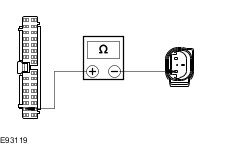
| | | Is the concern still evident? Yes REFER to: Noise, Vibration and Harshness (NVH) (100-04 Noise, Vibration and Harshness, Diagnosis and Testing). No Vehicle condition corrected. | | PINPOINT TEST C : VEHICLE LEAN | | TEST CONDITIONS | DETAILS/RESULTS/ACTIONS | | C1: VEHICLE LEAN | | | 1 Detach the load levelling shock absorbers from the wheel knuckles. | | | Does the vehicle lean? Yes Install new rear springs. REFER to: Spring (204-02 Rear Suspension, Removal and Installation).TEST the system for normal operation. No CARRY OUT the Load-Levelling Shock Absorber Component Test in this section. | | PINPOINT TEST D : SHOCK ABSORBER SOLENOID CIRCUIT - SHORT TO GROUND | | TEST CONDITIONS | DETAILS/RESULTS/ACTIONS | | D1: CHECK THE SHOCK ABSORBER SOLENOID SIGNAL RETURN CIRCUIT FOR SHORT TO GROUND | | | 1 Disconnect Adaptive Damping Module C4CD01-B. | | | 2 Disconnect Affected Shock Absorber Solenoid Connector. | | | 3 Measure the resistance between the following affected shock absorber solenoid connector pins, harness side and ground: - (Left front) C1CD03 pin 2, circuit RCD03B (VT/BN).
- (Right front) C1CD04 pin 2, circuit RCD04B (BU/OG).
- (Left rear) C4CD05 pin 2, circuit RCD05A (YE/BU).
- (Right rear) C4CD06 pin 2, circuit RCD06A (BU/BN).
| | | Is the resistance greater than 10,000 ohms (open circuit)? Yes INSTALL new front or rear shock absorbers as required.
REFER to: Shock Absorber and Spring Assembly (204-01 Front Suspension, Removal and Installation) /
Shock Absorber and Spring Assembly (204-01 Front Suspension, Disassembly and Assembly) /
Rear Shock Absorber (204-02 Rear Suspension, Removal and Installation).
TEST the system for normal operation. No REPAIR the circuit. TEST the system for normal operation. | | PINPOINT TEST E : SHOCK ABSORBER SOLENOID CIRCUIT - SHORT TO POWER | | TEST CONDITIONS | DETAILS/RESULTS/ACTIONS | | E1: CHECK THE SHOCK ABSORBER SOLENOID SIGNAL RETURN CIRCUIT FOR SHORT TO POWER | | | 1 Disconnect Adaptive Damping Module C4CD01-B. | | | 2 Disconnect Affected Shock Absorber Solenoid Connector. | | | 3 Ignition switch in position II. | | | 4 Measure the voltage between the following affected shock absorber solenoid connector pins, harness side and ground: - (Left front) C1CD03 pin 2, circuit RCD03B (VT/BN).
- (Right front) C1CD04 pin 2, circuit RCD04B (BU/OG).
- (Left rear) C4CD05 pin 2, circuit RCD05A (YE/BU).
- (Right rear) C4CD06 pin 2, circuit RCD06A (BU/BN).
| | | Is the voltage 0 volts? Yes INSTALL new front or rear shock absorbers as required.
REFER to: Shock Absorber and Spring Assembly (204-01 Front Suspension, Removal and Installation) /
Shock Absorber and Spring Assembly (204-01 Front Suspension, Disassembly and Assembly) /
Rear Shock Absorber (204-02 Rear Suspension, Removal and Installation).
TEST the system for normal operation. No REPAIR the circuit. TEST the system for normal operation. | | PINPOINT TEST F : SHOCK ABSORBER SOLENOID CIRCUIT - OPEN CIRCUIT | | TEST CONDITIONS | DETAILS/RESULTS/ACTIONS | | F1: CHECK THE SHOCK ABSORBER SOLENOID SIGNAL INPUT CIRCUIT FOR OPEN CIRCUIT | | | 1 Disconnect Adaptive Damping Module C4CD01-B. | | | 2 Disconnect Affected Shock Absorber Solenoid Connector. | | | 3 Measure the resistance between the following affected shock absorber solenoid connector pins, harness side and the adaptive damping module C4CD01-B pins, harness side: - (Left front) C1CD03 pin 1, circuit CCD03B (WH/BU) and C4CD01-B pin 6, circuit CCD03C (WH/BU).
- (Right front) C1CD04 pin 1, circuit CCD04B (GY/YE) and C4CD01-B pin 9, circuit CCD04C (GY/YE).
- (Left rear) C4CD05 pin 1, circuit CCD05A (GN/BU) and C4CD01-B pin 2, circuit CCD05B (GN/BU).
- (Right rear) C4CD06 pin 1, circuit CCD06A (VT/GY) and C4CD01-B pin 5, circuit CCD06B (VT/GY).
| | | Is the resistance less than 1 ohm? Yes No REPAIR the circuit. TEST the system for normal operation. | | F2: CHECK THE SHOCK ABSORBER SOLENOID RETURN CIRCUIT FOR OPEN CIRCUIT | | | 1 Measure the resistance between the following affected shock absorber solenoid connector pins, harness side and the adaptive damping module C4CD01-B pins, harness side: - (Left front) C1CD03 pin 2, circuit RCD03B (VT/BN) and C4CD01-B pin 7, circuit RCD03C (VT/BN).
- (Right front) C1CD04 pin 2, circuit RCD04B (BU/OG) and C4CD01-B pin 8, circuit RCD04C (BU/OG).
- (Left rear) C4CD05 pin 2, circuit RCD05A (YE/BU) and C4CD01-B pin 1, circuit RCD05B (YE/BU).
- (Right rear) C4CD06 pin 2, circuit RCD06A (BU/BN) and C4CD01-B pin 4, circuit RCD06B (BU/BN).
| | | Is the resistance less than 1 ohm? Yes INSTALL new front or rear shock absorbers as required.
REFER to: Shock Absorber and Spring Assembly (204-01 Front Suspension, Removal and Installation) /
Shock Absorber and Spring Assembly (204-01 Front Suspension, Disassembly and Assembly) /
Rear Shock Absorber (204-02 Rear Suspension, Removal and Installation).
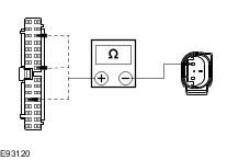
TEST the system for normal operation. No REPAIR the circuit. TEST the system for normal operation. | | PINPOINT TEST G : VERTICAL ACCELERATION SENSOR CIRCUIT - SHORT TO GROUND | | TEST CONDITIONS | DETAILS/RESULTS/ACTIONS | | G1: CHECK THE VERTICAL ACCELERATION SENSOR SIGNAL RETURN CIRCUIT FOR SHORT TO GROUND | | | 1 Disconnect Adaptive Damping Module C4CD01-B. | | | 2 Disconnect Affected Vertical Acceleration Sensor Connector. | | | 3 Measure the resistance between the following affected vertical acceleration sensor connector pins, harness side and ground: - (Left front) C1CD07 pin 1, circuit VCD07A (BN/WH).
- (Right front) C1CD08 pin 1, circuit VCD08A (BU/GY).
- (Left rear) C4CD09 pin 1, circuit VCD09B (YE/VT).
| | | Is the resistance greater than 10,000 ohms (open circuit)? Yes INSTALL new vertical acceleration sensors as required.
REFER to: Vehicle Front Vertical Accelerometer (204-05 Vehicle Dynamic Suspension, Removal and Installation) /
Vehicle Rear Vertical Accelerometer (204-05 Vehicle Dynamic Suspension, Removal and Installation).
TEST the system for normal operation. No REPAIR the circuit. TEST the system for normal operation. | | PINPOINT TEST H : VERTICAL ACCELERATION SENSOR CIRCUIT - SHORT TO POWER | | TEST CONDITIONS | DETAILS/RESULTS/ACTIONS | | H1: CHECK THE VERTICAL ACCELERATION SENSOR SIGNAL RETURN CIRCUIT FOR SHORT TO POWER | | | 1 Disconnect Adaptive Damping Module C4CD01-B. | | | 2 Disconnect Affected Vertical Acceleration Sensor Connector. | | | 3 Ignition switch in position II. | | | 4 Measure the voltage between the following affected vertical acceleration sensor connector pins, harness side and ground: - (Left front) C1CD07 pin 1, circuit VCD07A (BN/WH).
- (Right front) C1CD08 pin 1, circuit VCD08A (BU/GY).
- (Left rear) C4CD09 pin 1, circuit VCD09B (YE/VT).
| | | Is the voltage 0 volts? Yes INSTALL new vertical acceleration sensors as required.
REFER to: Vehicle Front Vertical Accelerometer (204-05 Vehicle Dynamic Suspension, Removal and Installation) /
Vehicle Rear Vertical Accelerometer (204-05 Vehicle Dynamic Suspension, Removal and Installation).
TEST the system for normal operation. No REPAIR the circuit. TEST the system for normal operation. | | PINPOINT TEST I : VERTICAL ACCELERATION SENSOR CIRCUIT - OPEN CIRCUIT | | TEST CONDITIONS | DETAILS/RESULTS/ACTIONS | | I1: CHECK THE VERTICAL ACCELERATION SENSOR SIGNAL INPUT CIRCUIT FOR OPEN CIRCUIT | | | 1 Disconnect Adaptive Damping Module C4CD01-B. | | | 2 Disconnect Affected Vertical Acceleration Sensor Connector. | | | 3 Measure the resistance between the following affected vertical acceleration sensor connector pins, harness side and the adaptive damping module C4CD01-B pin 13, circuit LCD02K (YE/GN): - (Left front) C1CD07 pin 3, circuit LCD02F (YE/GN).
- (Right front) C1CD08 pin 3, circuit LCD02E (YE/GN).
- (Left rear) C4CD09 pin 3, circuit LCD02J (YE/GN).
| | | Is the resistance less than 1 ohm? Yes No REPAIR the circuit. TEST the system for normal operation. | | I2: CHECK THE VERTICAL ACCELERATION SENSOR SIGNAL RETURN CIRCUIT FOR OPEN CIRCUIT | | | 1 Measure the resistance between the following affected vertical acceleration sensor connector pins, harness side and the adaptive damping module connector pins, harness side: - (Left front) C1CD07 pin 1, circuit VCD07A (BN/WH) and C4CD01-B pin 10, circuit VCD07B (BN/WH).
- (Right front) C1CD08 pin 1, circuit VCD08A (BU/GY) and C4CD01-B pin 22, circuit VCD08B (BU/GY).
- (Left rear) C4CD09 pin 1, circuit VCD09B (YE/VT) and C4CD01-B pin 17, circuit VCD09B (YE/VT).
| | | Is the resistance less than 1 ohm? Yes INSTALL new vertical acceleration sensors as required.
REFER to: Vehicle Front Vertical Accelerometer (204-05 Vehicle Dynamic Suspension, Removal and Installation) /
Vehicle Rear Vertical Accelerometer (204-05 Vehicle Dynamic Suspension, Removal and Installation).
TEST the system for normal operation. No REPAIR the circuit. TEST the system for normal operation. | | PINPOINT TEST J : SUSPENSION HEIGHT SENSOR CIRCUIT - SHORT TO GROUND | | TEST CONDITIONS | DETAILS/RESULTS/ACTIONS | | J1: CHECK THE SUSPENSION HEIGHT SENSOR SIGNAL RETURN CIRCUIT FOR SHORT TO GROUND | | | 1 Disconnect Adaptive Damping Module C4CD01-B. | | | 2 Disconnect Affected Suspension Height Sensor Connector. | | | 3 Measure the resistance between the following affected suspension height sensor connector pins, harness side and ground: - (Left front) C5CD07 pin 4, circuit VCD10B (BN).
- (Right front) C6CD08 pin 4, circuit VCD11B (GY/VT).
- (Left rear) C7CD12 pin 4, circuit VCD12B (VT/WH).
- (Right rear) C8CD13 pin 4, circuit VCD13B (GN/VT).
| | | Is the resistance greater than 10,000 ohms (open circuit)? Yes INSTALL new suspension height sensors as required.
REFER to: Front Suspension Height Sensor (204-05 Vehicle Dynamic Suspension, Removal and Installation) /
Rear Suspension Height Sensor (204-05 Vehicle Dynamic Suspension, Removal and Installation).
TEST the system for normal operation. No REPAIR the circuit. TEST the system for normal operation. | | PINPOINT TEST K : SUSPENSION HEIGHT SENSOR CIRCUIT - SHORT TO POWER | | TEST CONDITIONS | DETAILS/RESULTS/ACTIONS | | K1: CHECK THE SUSPENSION HEIGHT SENSOR SIGNAL RETURN CIRCUIT FOR SHORT TO POWER | | | 1 Disconnect Adaptive Damping Module C4CD01-B. | | | 2 Disconnect Affected Suspension Height Sensor Connector. | | | 3 Ignition switch in position II. | | | 4 Measure the voltage between the following affected suspension height sensor connector pins, harness side and ground: - (Left front) C5CD07 pin 4, circuit VCD10B (BN).
- (Right front) C6CD08 pin 4, circuit VCD11B (GY/VT).
- (Left rear) C7CD12 pin 4, circuit VCD12B (VT/WH).
- (Right rear) C8CD13 pin 4, circuit VCD13B (GN/VT).
| | | Is the voltage 0 volts? Yes INSTALL new suspension height sensors as required.
REFER to: Front Suspension Height Sensor (204-05 Vehicle Dynamic Suspension, Removal and Installation) /
Rear Suspension Height Sensor (204-05 Vehicle Dynamic Suspension, Removal and Installation).
TEST the system for normal operation. No REPAIR the circuit. TEST the system for normal operation. | | PINPOINT TEST L : SUSPENSION HEIGHT SENSOR CIRCUIT - OPEN CIRCUIT | | TEST CONDITIONS | DETAILS/RESULTS/ACTIONS | | L1: CHECK THE SUSPENSION HEIGHT SENSOR SIGNAL INPUT CIRCUIT FOR OPEN CIRCUIT | | | 1 Disconnect Adaptive Damping Module C4CD01-B. | | | 2 Disconnect Affected Suspension Height Sensor Connector. | | | 3 Measure the resistance between the following affected suspension height sensor connector pins, harness side and the adaptive damping module C4CD01-B pin 25, circuit LCD23E (GN/OG): - (Left front) C5CD07 pin 5, circuit LCD23B (GN/OG).
- (Right front) C6CD08 pin 5, circuit LCD02M (YE/GN).
- (Left rear) C7CD12 pin 5, circuit LCD23D (GN/OG).
- (Right rear) C8CD13 pin 5, circuit LCD02A (YE/GN).
| | | Is the resistance less than 1 ohm? Yes No REPAIR the circuit. TEST the system for normal operation. | | L2: CHECK THE SUSPENSION HEIGHT SENSOR SIGNAL RETURN CIRCUIT FOR OPEN CIRCUIT | | | 1 Measure the resistance between the following affected suspension height sensor connector pins, harness side and the adaptive damping module connector pins, harness side: - (Left front) C5CD07 pin 4, circuit VCD10B (BN) and C4CD01-B pin 12, circuit VCD10A (BN).
- (Right front) C6CD08 pin 4, circuit VCD11B (GY/VT) and C4CD01-B pin 27, circuit VCD11A (GY/VT).
- (Left rear) C7CD12 pin 4, circuit VCD12B (VT/WH) and C4CD01-B pin 28, circuit VCD12D (VT/WH).
- (Right rear) C8CD13 pin 4, circuit VCD13B (GN/VT) and C4CD01-B pin 14, circuit VCD14A (GN/VT).
| | | Is the resistance less than 1 ohm? Yes INSTALL new suspension height sensors as required.
REFER to: Front Suspension Height Sensor (204-05 Vehicle Dynamic Suspension, Removal and Installation) /
Rear Suspension Height Sensor (204-05 Vehicle Dynamic Suspension, Removal and Installation).
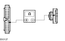
TEST the system for normal operation. No REPAIR the circuit. TEST the system for normal operation. | | PINPOINT TEST M : MODE INDICATOR CIRCUIT - SHORT TO GROUND | | TEST CONDITIONS | DETAILS/RESULTS/ACTIONS | | M1: CHECK THE ADAPTIVE DAMPING CONTROL SWITCH TO ADAPTIVE DAMPING MODULE CIRCUIT FOR SHORT TO GROUND | | | 1 Disconnect Adaptive Damping Module C4CD01-B. | | | 2 Disconnect Adaptive Damping Control Switch C2CD14. | | | 3 Measure the resistance between the following affected adaptive damping control switch connector pins, harness side and ground: - (Comfort) C2CD14 pin 2, circuit CCD18A (BU).
- (Normal) C2CD14A pin 6, circuit CCD17A (WH).
- (Sport) C2CD14A pin 5, circuit CCD16A (GY/OG).
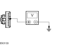
| | | Is the resistance greater than 10,000 ohms (open circuit)? Yes INSTALL a new adaptive damping control switch. TEST the system for normal operation. No REPAIR the circuit. TEST the system for normal operation. | | PINPOINT TEST N : MODE INDICATOR CIRCUIT - SHORT TO POWER | | TEST CONDITIONS | DETAILS/RESULTS/ACTIONS | | N1: CHECK THE ADAPTIVE DAMPING CONTROL SWITCH TO ADAPTIVE DAMPING MODULE CIRCUIT FOR SHORT TO GROUND | | | 1 Disconnect Adaptive Damping Module C4CD01-B. | | | 2 Disconnect Adaptive Damping Control Switch C2CD14. | | | 3 Ignition switch in position II. | | | 4 Measure the voltage between the following affected adaptive damping control switch connector pins, harness side and ground: - (Comfort) C2CD14 pin 2, circuit CCD18A (BU).
- (Normal) C2CD14A pin 6, circuit CCD17A (WH).
- (Sport) C2CD14A pin 5, circuit CCD16A (GY/OG).
| | | Is the voltage 0 volts? Yes INSTALL a new adaptive damping control switch. TEST the system for normal operation. No REPAIR the circuit. TEST the system for normal operation. | | PINPOINT TEST O : MODE INDICATOR CIRCUIT - OPEN CIRCUIT | | TEST CONDITIONS | DETAILS/RESULTS/ACTIONS | | O1: CHECK CIRCUITS CCD22A (BN/BU) AND CCD22B (BN/BU) FOR OPEN CIRCUIT | | | 1 Disconnect Adaptive Damping Module C4CD01-B. | | | 2 Disconnect Adaptive Damping Control Switch C2CD14. | | | 3 Measure the resistance between the adaptive damping module C4CD01-B pin 24, circuit CCD22B (BN/BU), harness side and the adaptive damping control switch C2CD14 pin 4, circuit CCD22A (BN/BU), harness side. | | | Is the resistance less than 1 ohm? Yes No REPAIR the circuit. TEST the system for normal operation. | | O2: CHECK THE ADAPTIVE DAMPING CONTROL SWITCH TO ADAPTIVE DAMPING MODULE CIRCUIT FOR OPEN CIRCUIT | | | 1 Measure the resistance between the following affected adaptive damping control switch connector pins, harness side and the adaptive damping module connector pins, harness side: - (Comfort) C2CD14 pin 2, circuit CCD18A (BU) and C4CD01-B pin 26, circuit CCD18B (BU).
- (Normal) C2CD14A pin 6, circuit CCD17A (WH) and C4CD01-B pin 11, circuit CCD17B (WH).
- (Sport) C2CD14A pin 5, circuit CCD16A (GY/OG) and C4CD01-B pin 29, circuit CCD16B (GY/OG).
| | | Is the resistance less than 1 ohm? Yes INSTALL a new adaptive damping control switch. TEST the system for normal operation. No REPAIR the circuit. TEST the system for normal operation. | | PINPOINT TEST P : SWITCH ILLUMINATION CIRCUIT - SHORT TO GROUND | | TEST CONDITIONS | DETAILS/RESULTS/ACTIONS | | P1: CHECK CIRCUITS CCD15A (WH/OG) AND CCD15B (WH/OG) FOR SHORT TO GROUND | | | 1 Disconnect Adaptive Damping Module C4CD01-B. | | | 2 Disconnect Adaptive Damping Control Switch C2CD14. | | | 3 Measure the resistance between the adaptive damping control switch C2CD14 pin 3, circuit CCD15A (WH/OG), harness side and ground. | | | Is the resistance greater than 10,000 ohms (open circuit)? Yes INSTALL a new adaptive damping control switch. TEST the system for normal operation. No REPAIR the circuit. TEST the system for normal operation. | | PINPOINT TEST Q : SWITCH ILLUMINATION CIRCUIT - SHORT TO POWER | | TEST CONDITIONS | DETAILS/RESULTS/ACTIONS | | Q1: CHECK CIRCUITS CCD15A (WH/OG) AND CCD15B (WH/OG) FOR SHORT TO POWER | | | 1 Disconnect Adaptive Damping Module C4CD01-B. | | | 2 Disconnect Adaptive Damping Control Switch C2CD14. | | | 3 Ignition switch in position II. | | | 4 Measure the voltage between the adaptive damping control switch C2CD14 pin 3, circuit CCD15A (WH/OG), harness side and ground. | | | Is the voltage 0 volts? Yes INSTALL a new adaptive damping control switch. TEST the system for normal operation. No REPAIR the circuit. TEST the system for normal operation. | | PINPOINT TEST R : SWITCH ILLUMINATION CIRCUIT - OPEN CIRCUIT | | TEST CONDITIONS | DETAILS/RESULTS/ACTIONS | | R1: CHECK CIRCUITS CCD15A (WH/OG) AND CCD15B (WH/OG) FOR OPEN CIRCUIT | | | 1 Disconnect Adaptive Damping Module C4CD01-B. | | | 2 Disconnect Adaptive Damping Control Switch C2CD14. | | | 3 Measure the resistance between the adaptive damping control switch C2CD14 pin 3, circuit CCD15A (WH/OG), harness side and the adaptive damping module C4CD01-B pin 3, circuit CCD15B (WH/OG), harness side. | | | Is the resistance less than 1 ohm? Yes No REPAIR the circuit. TEST the system for normal operation. | | R2: CHECK CIRCUITS RCD21A (VT/OG) AND RCD21B (VT/OG) FOR OPEN CIRCUIT | | | 1 Measure the resistance between the adaptive damping control switch C2CD14 pin 1, circuit RCD21A (VT/OG), harness side and the adaptive damping module C4CD01-B pin 21, circuit RDC21B (VT/OG), harness side. | | | Is the resistance less than 1 ohm? Yes INSTALL a new adaptive damping control switch. TEST the system for normal operation. No REPAIR the circuit. TEST the system for normal operation. | | PINPOINT TEST S : SWITCH CIRCUIT - SHORT TO GROUND | | TEST CONDITIONS | DETAILS/RESULTS/ACTIONS | | S1: CHECK CIRCUITS CCD22A (BN/BU) AND CCD22B (BN/BU) FOR OPEN CIRCUIT | | | 1 Disconnect Adaptive Damping Module C4CD01-B. | | | 2 Disconnect Adaptive Damping Control Switch C2CD14. | | | 3 Measure the resistance between the adaptive damping control switch C2CD14 pin 4, circuit CCD22A (BN/BU), harness side and ground. | | | Is the resistance greater than 10,000 ohms (open circuit)? Yes INSTALL a new adaptive damping control switch. TEST the system for normal operation. No REPAIR the circuit. TEST the system for normal operation. | | PINPOINT TEST T : SWITCH CIRCUIT - SHORT TO POWER | | TEST CONDITIONS | DETAILS/RESULTS/ACTIONS | | T1: CHECK CIRCUITS CCD22A (BN/BU) AND CCD22B (BN/BU) FOR SHORT TO POWER | | | 1 Disconnect Adaptive Damping Module C4CD01-B. | | | 2 Disconnect Adaptive Damping Control Switch C2CD14. | | | 3 Ignition switch in position II. | | | 4 Measure the voltage between the adaptive damping control switch C2CD14 pin 4, circuit CCD22A (BN/BU), harness side and ground. | | | Is the voltage 0 volts? Yes INSTALL a new adaptive damping control switch. TEST the system for normal operation. No REPAIR the circuit. TEST the system for normal operation. | | PINPOINT TEST U : SWITCH CIRCUIT - OPEN CIRCUIT | | TEST CONDITIONS | DETAILS/RESULTS/ACTIONS | | U1: CHECK CIRCUITS CCD22A (BN/BU) AND CCD22B (BN/BU) FOR OPEN CIRCUIT | | | 1 Disconnect Adaptive Damping Module C4CD01-B. | | | 2 Disconnect Adaptive Damping Control Switch C2CD14. | | | 3 Measure the resistance between the adaptive damping control switch C2CD14 pin 4, circuit CCD22A (BN/BU), harness side and the adaptive damping module C4CD01-B pin 24, circuit CCD22B (BN/BU), harness side. | | | Is the resistance less than 1 ohm? Yes No REPAIR the circuit. TEST the system for normal operation. | | U2: CHECK CIRCUITS RCD21A (VT/OG) AND RCD21B (VT/OG) FOR OPEN CIRCUIT | | | 1 Measure the resistance between the adaptive damping control switch C2CD14 pin 1, circuit RCD21A (VT/OG), harness side and the adaptive damping module C4CD01-B pin 21, circuit RDC21B (VT/OG), harness side. | | | Is the resistance less than 1 ohm? Yes INSTALL a new adaptive damping control switch. TEST the system for normal operation. No REPAIR the circuit. TEST the system for normal operation. | Component Tests Raise and support the vehicle. REFER to: Lifting (100-02 Jacking and Lifting, Description and Operation). Ball Joint Inspection - Firmly grasp the outer end of the suspension lower arm and try to move it up and down, watching and feeling for any movement. Free movement will usually be accompanied by an audible "click''. There should be no free movement.
- If there is any free movement install a new lower arm.
REFER to: Lower Arm (204-01 Front Suspension, Removal and Installation).
- If a new lower arm is installed it will be necessary to check and adjust the front wheel alignment.
REFER to: Specifications (204-00 Suspension System - General Information, Specifications).
Strut or Shock Absorber Inspection NOTE:Inspect the struts or shock absorber for signs of oil weepage or leaks. Make sure that the oil is not from another source. Weepage: - deposits a thin film of oil on the strut and spring assembly or shock absorber.
- is normally noticed due to a collection of dust on the strut and spring assembly or shock absorber.
- occurs during the normal running-in period of 4800 - 8050 km. After this period no new signs of oil should be visible.
- does not require new struts or shock absorbers to be installed.
Leakage: - covers the entire strut and spring assembly or shock absorber with oil.
- will drip oil onto the surrounding suspension components.
- requires new struts or shock absorbers to be installed.
Strut or Shock Absorber Testing NOTE:Struts or shock absorbers must be tested in the vertical position. - Remove both strut and spring assemblies or shock absorbers. The piston rods should extend.
- Disassemble the strut and spring assemblies. REFER to: Shock Absorber and Spring Assembly (204-01 Front Suspension, Disassembly and Assembly).
- Compress the piston rods. Both piston rods should offer the same resistance when compressing.
- Compress and release the piston rods. The piston rods should extend equally.
- Compress and pull the piston rod in the vertical position. Feel if the resistance force at the point of direction change-over is perceptible without a lag. If a lag is perceptible it is an indication of shock absorber valve damage and new struts or shock absorbers must be installed. REFER to:
Shock Absorber and Spring Assembly (204-01 Front Suspension, Removal and Installation), Rear Shock Absorber (204-02 Rear Suspension, Removal and Installation). Load-Levelling Shock Absorber - With the vehicle unladen, measure and note the dimensions between the base of the wheel rim and the top of the rear fender on both sides.
- The measurements on both sides should be approximately equal.
- With a load of 4 average size adults and a 100 kg weight, measure and note the dimensions between the base of the wheel rim and the top of the rear fender on both sides.
-
NOTE:Due to the internal ratchet mechanism of the suspension components, the height of the rear of the vehicle should rise during the road test. With a load of 4 average size adults and a 100 kg weight, drive the vehicle for 3 km on a road of normal condition. - With a load of 4 average size adults and a 100 kg weight, measure and note the dimensions between the base of the wheel rim and the top of the rear fender on both sides.
- If the dimensions on both sides are no longer approximately equal, install new load levelling shock absorbers.
REFER to: Rear Shock Absorber (204-02 Rear Suspension, Removal and Installation).
-
NOTE:Due to the internal ratchet mechanism of the suspension components, the height of the rear of the vehicle should rise during the road test. If the dimensions are approximately equal, unload the vehicle and drive the vehicle for 3 km on a road of normal condition. - With the vehicle unladen, measure and note the dimensions between the base of the wheel rim and the top of the rear fender on both sides. Check the final dimensions with the original dimensions taken in the unladen condition.
- If the final dimensions do not approximately equal the original dimensions, install new load levelling shock absorbers.
REFER to: Rear Shock Absorber (204-02 Rear Suspension, Removal and Installation).
- If the final dimensions approximately equal the original dimensions, verify the customer concern.
| |