| Diagnosis and Testing Principles of Operation Inspection and Verification - Verify the customer concern.
- Visually inspect for obvious signs of mechanical or electrical damage.
Visual Inspection Chart | Mechanical | Electrical | | Window seal | Fuse(s) | | Door window frame | Door module(s) | | | Electrical connector(s) | | | Switch(es) | | | Grid wire(s) | | | Circuit(s) | - If an obvious cause for an observed or reported concern is found, correct the cause (if possible) before proceeding to the next step
- If the cause is not visually evident, verify the symptom and refer to the Symptom Chart.
Symptom Chart | Symptom | Possible Sources | Action | | A single power window is inoperative - Driver side | * Driver side front door switch. * Door module. * LIN bus. | * REFER to WDS. | | * Door window regulator motor. * Circuit(s). | * | | A single power window is inoperative - Passenger side | * Door module. * LIN bus. | * REFER to WDS. | | * Passenger power window switch. * Door window regulator motor. * Circuit(s). | * | | The one-touch down feature is inoperative | * Driver side front door switch. * Door module. | * REFER to WDS. | | * Passenger power window switch. | * CARRY OUT the Passenger Power Window Switch component test. REFER to the Wiring Diagrams. | | The defrost system is inoperative | * Central junction box (CJB). * Engine junction box (EJB). * Rear junction box (RJB). | * REFER to WDS. | | * Heated windshield glass switch. | * CARRY OUT the Heated Windshield Glass Switch component test. REFER to the Wiring Diagrams. | | * Heated rear window glass switch. | * CARRY OUT the Heated Rear Window Glass Switch component test. REFER to the Wiring Diagrams. | | * Heated rear window grid wire. | * CARRY OUT the Heated Rear Window Grid Wire component test in this procedure. | | * Heated windshield grid wire. * Circuit(s) | * | | The defrost system will not shut off automatically | * Central junction box (CJB). | * REFER to WDS. | | * Circuit(s) | * | | The global open/closing function is inoperative/does not operate correctly | * Central junction box (CJB). * LIN bus. | * REFER to WDS. | Pinpoint Tests | PINPOINT TEST A : A SINGLE POWER WINDOW IS INOPERATIVE - DRIVER SIDE | | TEST CONDITIONS | DETAILS/RESULTS/ACTIONS | | A1: CHECK THE DRIVER SIDE FRONT DOOR SWITCH | | | 1 Ignition switch in position II. | | | 2 Operate the power mirror switch. | | | Do the power mirrors operate? Yes No | | A2: CHECK FOR CONTINUITY BETWEEN THE DRIVER DOOR MODULE AND THE DRIVER SIDE FRONT DOOR WINDOW REGULATOR MOTOR - DOWN CIRCUIT | NOTE:Use a digital multimeter for all electrical measurements. | | | 1 Ignition switch in position 0. | | | 2 Disconnect Driver Door Module C5PL01-A. | | | 3 Disconnect Driver Door Window Regulator Motor C5PW11. | | | 4 Measure the resistance between the driver door module C5PL01-A pin 1, circuit CPW35A (GN), harness side and the driver side front door window regulator motor C5PW11 pin 5, circuit CPW35B (GN), harness side. | | | Is the resistance less than 5 ohms? Yes No REPAIR circuit CPW35A (GN) or circuit CPW35B (GN). TEST the system for normal operation. | | A3: CHECK FOR CONTINUITY BETWEEN THE DRIVER DOOR MODULE AND THE DRIVER SIDE FRONT DOOR WINDOW REGULATOR MOTOR - UP CIRCUIT | | | 1 Measure the resistance between the driver door module C5PL01-A pin 12, circuit CPW34A (BU), harness side and the driver side front door window regulator motor C5PW11 pin 6, circuit CPW34B (BU), harness side. | | | Is the resistance less than 5 ohms? Yes No REPAIR circuit CPW34A (BU) or circuit CPW34B (BU). TEST the system for normal operation. | | A4: CHECK FOR CONTINUITY BETWEEN THE DRIVER DOOR MODULE AND THE DRIVER SIDE FRONT DOOR WINDOW REGULATOR MOTOR - HALL SENSOR SUPPLY CIRCUIT | | | 1 Measure the resistance between the driver door module C5PL01-A pin 17, circuit LPW36A (WH/BN), harness side and the driver side front door window regulator motor C5PW11 pin 2, circuit LPW36B (WH/BN), harness side. | | | Is the resistance less than 5 ohms? Yes No REPAIR circuit LPW36A (WH/BN) or circuit LPW36B (WH/BN). TEST the system for normal operation. | | A5: CHECK FOR CONTINUITY BETWEEN THE DRIVER DOOR MODULE AND THE DRIVER SIDE FRONT DOOR WINDOW REGULATOR MOTOR - HALL SENSOR GROUND CIRCUIT | | | 1 Measure the resistance between the driver door module C5PL01-A pin 16, circuit RPW37A (VT/GN), harness side and the driver side front door window regulator motor C5PW11 pin 1, circuit RPW37B (VT/GN), harness side. | | | Is the resistance less than 5 ohms? Yes No REPAIR circuit RPW37A (VT/GN) or circuit RPW37B (VT/GN). TEST the system for normal operation. | | A6: CHECK FOR CONTINUITY BETWEEN THE DRIVER DOOR MODULE AND THE DRIVER SIDE FRONT DOOR WINDOW REGULATOR MOTOR - HALL SENSOR 1 CIRCUIT | | | 1 Measure the resistance between the driver door module C5PL01-A pin 6, circuit VPW38A (YE/BU), harness side and the driver side front door window regulator motor C5PW11 pin 3, circuit VPW38B (YE/BU), harness side. | | | Is the resistance less than 5 ohms? Yes No REPAIR circuit VPW38A (YE/BU) or circuit VPW38B (YE/BU). TEST the system for normal operation. | | A7: CHECK FOR CONTINUITY BETWEEN THE DRIVER DOOR MODULE AND THE DRIVER SIDE FRONT DOOR WINDOW REGULATOR MOTOR - HALL SENSOR 2 CIRCUIT | | | 1 Measure the resistance between the driver door module C5PL01-A pin 5, circuit VPW39A (BU/WH), harness side and the driver side front door window regulator motor C5PW11 pin 4, circuit VPW39B (BU/WH), harness side. | | | Is the resistance less than 5 ohms? Yes Install a new driver side front door window regulator motor.
REFER to: Door Window Regulator Motor (501-11 Glass, Frames and Mechanisms, Removal and Installation).
TEST the system for normal operation. No REPAIR circuit VPW39A (BU/WH) or circuit VPW39B (BU/WH). TEST the system for normal operation. | | A8: CHECK FOR CONTINUITY BETWEEN THE DRIVER SIDE FRONT DOOR SWITCH AND GROUND | | | 1 Ignition switch in position 0. | | | 2 Disconnect Driver Side Front Door Switch C5PL22. | | | 3 Measure the resistance between the driver side front door switch C5PL22 pin 4, circuit GD135H (BK/GY), harness side and ground. | | | Is the resistance less than 5 ohms? Yes No REPAIR circuit GD135H (BK/GY). TEST the system for normal operation. | | A9: CHECK FOR VOLTAGE TO THE DRIVER SIDE FRONT DOOR SWITCH | | | 1 Ignition switch in position II. | | | 2 Measure the voltage between the driver side door switch C5PL22 pin 1, circuit A_CBP17H (BN/GN), harness side and ground. | | | Is the voltage greater than 10 volts? Yes No REPAIR circuit A_CBP17H (BN/GN). TEST the system for normal operation. | | A10: CHECK FOR CONTINUITY BETWEEN THE DRIVER DOOR MODULE AND THE DRIVER SIDE FRONT DOOR SWITCH | | | 1 Ignition switch in position 0. | | | 2 Disconnect Driver Door Module C5PL01-A. | | | 3 Measure the resistance between the driver door module C5PL01-A pin 20, circuit VPW32D (GY/BU), harness side and the driver side front door switch C5PL22 pin 3, circuit VPW32D (GY/BU), harness side. | | | Is the resistance less than 5 ohms? Yes CHECK the driver door module. REFER to WDS. CHECK the driver side front door switch. REFER to WDS. No REPAIR circuit VPW32D (GY/BU). TEST the system for normal operation. | | PINPOINT TEST B : A SINGLE POWER WINDOW IS INOPERATIVE - PASSENGER SIDE | | TEST CONDITIONS | DETAILS/RESULTS/ACTIONS | | B1: DOES THE PASSENGER WINDOW OPERATE FROM THE DRIVER SIDE FRONT DOOR SWITCH | NOTE:Use a digital multimeter for all electrical measurements. | | | 1 Ignition switch in position II. | | | 2 Operate the passenger power window from the driver side front door switch. | | | Does the passenger power window operate? Yes No | | B2: CHECK FOR CONTINUITY BETWEEN THE PASSENGER POWER WINDOW SWITCH AND THE PASSENGER DOOR MODULE SWITCH GROUND CIRCUIT | | | 1 Ignition switch in position 0. | | | 2 Disconnect Passenger Power Window Switch C6PW19 or C7PW21 or C8PW23. | | | 3 Disconnect Passenger Door Module C6PL01-A or C7PL01 or C8PL01. | | | 4 Measure the resistance between the: - Inoperative front passenger power window - passenger power window switch C6PW19 pin 4, circuit RPW05A (GN/BN), harness side and the passenger door module C6PL01-A pin 18, circuit RPW05A (GN/BN), harness side.
- Inoperative left-hand rear passenger power window - passenger power window switch C8PW23 pin 4, circuit RPW07A (GY/OG), harness side and the passenger door module C7PL01 pin 18, circuit RPW07A (GY/OG), harness side.
- Inoperative right-hand rear passenger power window - passenger power window switch C7PW21 pin 4, circuit RPW09A (BN/WH), harness side and the passenger door module C8PL01 pin 18, circuit RPW09A (BN/WH), harness side.
| | | Is the resistance less than 5 ohms? Yes No Inoperative front passenger power window - REPAIR circuit RPW05A (GN/BN). TEST the system for normal operation. Inoperative left-hand rear passenger power window - REPAIR circuit RPW07A (GY/OG). TEST the system for normal operation. Inoperative right-hand rear passenger power window - REPAIR circuit RPW09A (BN/WH). TEST the system for normal operation. | | B3: CHECK FOR CONTINUITY BETWEEN THE PASSENGER POWER WINDOW SWITCH AND THE PASSENGER DOOR MODULE UP CIRCUIT | | | 1 Measure the resistance between the: - Inoperative front passenger power window - passenger power window switch C6PW19 pin 2, circuit RPW13A (BN/YE), harness side and the passenger door module C6PL01-A pin 22, circuit RPW13A (BN/YE), harness side.
- Inoperative left-hand rear passenger power window - passenger power window switch C8PW23 pin 2, circuit RPW16A (BU/OG), harness side and the passenger door module C7PL01 pin 22, circuit RPW16A (BU/OG), harness side.
- Inoperative right-hand rear passenger power window - passenger power window switch C7PW21 pin 2, circuit RPW18A (GY/VT), harness side and the passenger door module C8PL01 pin 22, circuit RPW18A (GY/VT), harness side.
| | | Is the resistance less than 5 ohms? Yes No Inoperative front passenger power window - REPAIR circuit RPW13A (BN/YE). TEST the system for normal operation. Inoperative left-hand rear passenger power window - REPAIR circuit RPW16A (BU/OG). TEST the system for normal operation. Inoperative right-hand rear passenger power window - REPAIR circuit RPW18A (GY/VT). TEST the system for normal operation. | | B4: CHECK FOR CONTINUITY BETWEEN THE PASSENGER POWER WINDOW SWITCH AND THE PASSENGER DOOR MODULE DOWN CIRCUIT | | | 1 Measure the resistance between the: - Inoperative front passenger power window - passenger power window switch C6PW19 pin 3, circuit RPW12A (GN/OG), harness side and the passenger door module C6PL01-A pin 11, circuit RPW12A (GN/OG), harness side.
- Inoperative left-hand rear passenger power window - passenger power window switch C8PW23 pin 3, circuit RPW15A (YE), harness side and the passenger door module C7PL01 pin 11, circuit RPW15A (YE), harness side.
- Inoperative right-hand rear passenger power window - passenger power window switch C7PW21 pin 3, circuit RPW17A (BN/GN), harness side and the passenger door module C8PL01 pin 11, circuit RPW17A (BN/GN), harness side.
| | | Is the resistance less than 5 ohms? Yes CARRY OUT the Passenger Power Window Switch component test. REFER to the Wiring Diagrams. CHECK the passenger door module. REFER to WDS. No Inoperative front passenger power window - REPAIR circuit RPW12A (GN/OG). TEST the system for normal operation. Inoperative left-hand rear passenger power window - REPAIR circuit RPW15A (YE). TEST the system for normal operation. Inoperative right-hand rear passenger power window - REPAIR circuit RPW17A (BN/GN). TEST the system for normal operation. | | B5: CHECK FOR CONTINUITY BETWEEN THE PASSENGER DOOR MODULE AND THE PASSENGER WINDOW REGULATOR MOTOR DOWN CIRCUIT | | | 1 Ignition switch in position 0. | | | 2 Disconnect Passenger Door Module C6PL01-A or C7PL01 or C8PL01. | | | 3 Disconnect Passenger Door Window Regulator Motor C6PW20 or C7PW22 or C8PW24. | | | 4 Measure the resistance between the: - Inoperative front passenger power window - passenger door module C6PL01-A pin 1, circuit CPW41A (GY/YE), harness side, harness side and the door window regulator motor C6PW20 pin 5, circuit CPW41B (GY/YE), harness side.
- Inoperative left-hand rear passenger power window - passenger door module C7PL01-A pin 1, circuit CPW47A (VT/OG), harness side and the door window regulator motor C7PW22 pin 5, circuit CPW47A (VT/OG), harness side.
- Inoperative right-hand rear passenger power window - passenger door module C8PL01-A pin 1, circuit CPW53A (YE/OG), harness side and the door window regulator motor C8PW24 pin 5, circuit CPW53A (YE/OG), harness side.
| | | Is the resistance less than 5 ohms? Yes No Inoperative front passenger power window - REPAIR circuit CPW41A (GY/YE) or circuit CPW41B (GY/YE). TEST the system for normal operation. Inoperative left-hand rear passenger power window - REPAIR circuit CPW47A (VT/OG). TEST the system for normal operation. Inoperative right-hand rear passenger power window - REPAIR circuit CPW53A (YE/OG). TEST the system for normal operation. | | B6: CHECK FOR CONTINUITY BETWEEN THE PASSENGER DOOR MODULE AND THE PASSENGER WINDOW REGULATOR MOTOR UP CIRCUIT | | | 1 Ignition switch in position 0. | | | 2 Disconnect Passenger Door Module C6PL01-A or C7PL01 or C8PL01. | | | 3 Measure the resistance between the: - Inoperative front passenger power window - passenger door module C6PL01-A pin 12, circuit CPW40A (WH), harness side, harness side and the door window regulator motor C6PW20 pin 6, circuit CPW40B (WH), harness side.
- Inoperative left-hand rear passenger power window - passenger door module C7PL01-A pin 12, circuit CPW46A (GY/BN), harness side and the door window regulator motor C7PW22 pin 6, circuit CPW46A (GY/BN), harness side.
- Inoperative right-hand rear passenger power window - passenger door module C8PL01-A pin 12, circuit CPW52A (VT/WH), harness side and the door window regulator motor C8PW24 pin 6, circuit CPW52A (VT/WH), harness side.
| | | Is the resistance less than 5 ohms? Yes No Inoperative front passenger power window - REPAIR circuit CPW40A (WH) or circuit CPW40B (WH). TEST the system for normal operation. Inoperative left-hand rear passenger power window - REPAIR circuit CPW46A (GY/BN). TEST the system for normal operation. Inoperative right-hand rear passenger power window - REPAIR circuit CPW52A (VT/WH). TEST the system for normal operation. | | B7: CHECK FOR CONTINUITY BETWEEN THE PASSENGER DOOR MODULE AND THE PASSENGER WINDOW REGULATOR MOTOR - HALL SENSOR SUPPLY CIRCUIT | | | 1 Measure the resistance between the: - Inoperative front passenger power window - passenger door module C6PL01-A pin 17, circuit LPW42A (VT/GY), harness side, harness side and the door window regulator motor C6PW20 pin 2, circuit LPW42B (VT/GY), harness side.
- Inoperative left-hand rear passenger power window - passenger door module C7PL01-A pin 17, circuit LPW48A (YE/GY), harness side and the door window regulator motor C7PW22 pin 2, circuit LPW48A (YE/GY), harness side.
- Inoperative right-hand rear passenger power window - passenger door module C8PL01-A pin 17, circuit LPW54A (BN/GN), harness side and the door window regulator motor C8PW24 pin 2, circuit LPW54A (BN/GN), harness side.
| | | Is the resistance less than 5 ohms? Yes No Inoperative front passenger power window - REPAIR circuit LPW42A (VT/GY) or circuit LPW42B (VT/GY). TEST the system for normal operation. Inoperative left-hand rear passenger power window - REPAIR circuit LPW48A (YE/GY). TEST the system for normal operation. Inoperative right-hand rear passenger power window - REPAIR circuit LPW54A (BN/GN). TEST the system for normal operation. | | B8: CHECK FOR CONTINUITY BETWEEN THE DRIVER DOOR MODULE AND THE DRIVER SIDE FRONT DOOR WINDOW REGULATOR MOTOR - HALL SENSOR GROUND CIRCUIT | | | 1 Measure the resistance between the: - Inoperative front passenger power window - passenger door module C6PL01-A pin 16, circuit RPW43A (YE/GN), harness side, harness side and the door window regulator motor C6PW20 pin 1, circuit RPW43B (YE/GN), harness side.
- Inoperative left-hand rear passenger power window - passenger door module C7PL01-A pin 16, circuit RPW49A (BU/BN), harness side and the door window regulator motor C7PW22 pin 1, circuit RPW49A (BU/BN), harness side.
- Inoperative right-hand rear passenger power window - passenger door module C8PL01-A pin 16, circuit RPW55A (GY/VT), harness side and the door window regulator motor C8PW24 pin 1, circuit RPW55A (GY/VT), harness side.
| | | Is the resistance less than 5 ohms? Yes No Inoperative front passenger power window - REPAIR circuit RPW43A (YE/GN) or circuit RPW43B (YE/GN). TEST the system for normal operation. Inoperative left-hand rear passenger power window - REPAIR circuit RPW49A (BU/BN). TEST the system for normal operation. Inoperative right-hand rear passenger power window - REPAIR circuit RPW55A (GY/VT). TEST the system for normal operation. | | B9: CHECK FOR CONTINUITY BETWEEN THE DRIVER DOOR MODULE AND THE DRIVER SIDE FRONT DOOR WINDOW REGULATOR MOTOR - HALL SENSOR 1 CIRCUIT | | | 1 Measure the resistance between the: - Inoperative front passenger power window - passenger door module C6PL01-A pin 6, circuit VPW44A (BU/OG), harness side, harness side and the door window regulator motor C6PW20 pin 3, circuit VPW44B (BU/OG), harness side.
- Inoperative left-hand rear passenger power window - passenger door module C7PL01-A pin 6, circuit VPW50A (GN/OG), harness side and the door window regulator motor C7PW22 pin 3, circuit VPW50A (GN/OG), harness side.
- Inoperative right-hand rear passenger power window - passenger door module C8PL01-A pin 6, circuit VPW56A (BN/BU), harness side and the door window regulator motor C8PW24 pin 3, circuit VPW56A (BN/BU), harness side.
| | | Is the resistance less than 5 ohms? Yes No Inoperative front passenger power window - REPAIR circuit VPW44A (BU/OG) or circuit VPW44B (BU/OG). TEST the system for normal operation. Inoperative left-hand rear passenger power window - REPAIR circuit VPW50A (GN/OG). TEST the system for normal operation. Inoperative right-hand rear passenger power window - REPAIR circuit VPW56A (BN/BU). TEST the system for normal operation. | | B10: CHECK FOR CONTINUITY BETWEEN THE DRIVER DOOR MODULE AND THE DRIVER SIDE FRONT DOOR WINDOW REGULATOR MOTOR - HALL SENSOR 2 CIRCUIT | | | 1 Measure the resistance between the: - Inoperative front passenger power window - passenger door module C6PL01-A pin 5, circuit VPW45A (GN/WH), harness side, harness side and the door window regulator motor C6PW20 pin 4, circuit VPW45B (GN/WH), harness side.
- Inoperative left-hand rear passenger power window - passenger door module C7PL01-A pin 5, circuit VPW51A (BN/YE), harness side and the door window regulator motor C7PW22 pin 4, circuit VPW51A (BN/YE), harness side.
- Inoperative right-hand rear passenger power window - passenger door module C8PL01-A pin 5, circuit VPW57A (BU/GY), harness side and the door window regulator motor C8PW24 pin 4, circuit VPW57A (BU/GY), harness side.
| | | Is the resistance less than 5 ohms? Yes Install a new driver side front door window regulator motor.
REFER to: Door Window Regulator Motor (501-11 Glass, Frames and Mechanisms, Removal and Installation).
TEST the system for normal operation. No Inoperative front passenger power window - REPAIR circuit VPW45A (GN/WH) or circuit VPW45B (GN/WH). TEST the system for normal operation. Inoperative left-hand rear passenger power window - REPAIR circuit VPW51A (BN/YE). TEST the system for normal operation. Inoperative right-hand rear passenger power window - REPAIR circuit VPW57A (BU/GY). TEST the system for normal operation. | | PINPOINT TEST C : A SINGLE POWER WINDOW IS INOPERATIVE - REAR QUARTER WINDOW | | TEST CONDITIONS | DETAILS/RESULTS/ACTIONS | | C1: CHECK FOR VOLTAGE TO THE REAR QUARTER POWER WINDOW SWITCH | NOTE:Use a digital multimeter for all electrical measurements. | | | 1 Disconnect Rear Quarter Power Window Switch C7PW25-B or C8PW27-B. | | | 2 Ignition switch in position II. | | | 3 Measure the voltage between the: - Inoperative left-hand rear quarter power window - quarter power window switch C7PW25-B pin 2, circuit CPW30C (GY/YE), harness side and ground.
- Inoperative right-hand rear quarter power window - quarter power window switch C8PW27-B pin 2, circuit CPW30A (GY/YE), harness side and ground.
| | | Is the voltage greater than 10 volts? Yes No Inoperative left-hand rear quarter power window - REPAIR circuit CPW30C (GY/YE). TEST the system for normal operation. Inoperative right-hand rear quarter power window - REPAIR circuit CPW30A (GY/YE). TEST the system for normal operation. | | C2: CHECK FOR CONTINUITY BETWEEN THE REAR QUARTER POWER WINDOW SWITCH AND GROUND | | | 1 Ignition switch in position 0. | | | 2 Measure the resistance between the: | | | Is the resistance less than 5 ohms? Yes No Inoperative left-hand rear quarter power window - REPAIR circuit GD152AR (BK/BU). TEST the system for normal operation. Inoperative right-hand rear quarter power window - REPAIR circuit GD152AU (BK/BU). TEST the system for normal operation. | | C3: CHECK FOR CONTINUITY BETWEEN THE REAR QUARTER POWER WINDOW SWITCH AND THE QUARTER POWER WINDOW MOTOR | | | 1 Disconnect Rear Quarter Power Window Motor C7PW26 or C8PW28. | | | 2 Measure the resistance between the: - Inoperative left-hand rear quarter power window - rear quarter power window switch C7PW25-B pin 1, circuit CPW25B (YE/BU), harness side and the rear quarter power window motor C7PW26 pin 3, circuit CPW25B (YE/BU), harness side.
- Inoperative right-hand rear quarter power window - rear quarter power window switch C8PW27-B pin 1, circuit CPW27A (GN), harness side and the rear quarter power window motor C8PW28 pin 3, circuit CPW27A (GN), harness side.
| | | Is the resistance less than 5 ohms? Yes No Inoperative left-hand rear quarter power window - REPAIR circuit CPW25B (YE/BU). TEST the system for normal operation. Inoperative right-hand rear quarter power window - REPAIR circuit CPW27A (GN). TEST the system for normal operation. | | C4: CHECK FOR CONTINUITY BETWEEN THE REAR QUARTER POWER WINDOW SWITCH AND THE QUARTER POWER WINDOW MOTOR | | | 1 Measure the resistance between the: - Inoperative left-hand rear quarter power window - rear quarter power window switch C7PW25-B pin 7, circuit CPW26B (BU/BN), harness side and the rear quarter power window motor C7PW26 pin 1, circuit CPW26B (BU/BN), harness side.
- Inoperative right-hand rear quarter power window - rear quarter power window switch C8PW27-B pin 7, circuit CPW28A (WH/BN), harness side and the rear quarter power window motor C8PW28 pin 1, circuit CPW28A (WH/BN), harness side.
| | | Is the resistance less than 5 ohms? Yes Install a new rear quarter window regulator motor.
REFER to: Rear Quarter Window Regulator Motor (501-11 Glass, Frames and Mechanisms, Removal and Installation).
TEST the system for normal operation. No Inoperative left-hand rear quarter power window - REPAIR circuit CPW26B (BU/BN). TEST the system for normal operation. Inoperative right-hand rear quarter power window - REPAIR circuit CPW28A (WH/BN). TEST the system for normal operation. | | PINPOINT TEST D : THE DEFROST SYSTEM IS INOPERATIVE | | TEST CONDITIONS | DETAILS/RESULTS/ACTIONS | | D1: CHECK THE OPERATION OF THE HEATED REAR WINDOW | NOTE:Use a digital multimeter for all electrical measurements. | | | 1 Ignition switch in position III. | | | 2 Ignition switch in position II. | | | 3 Operate the heated rear window switch. | | | Does the heated rear window function correctly? Yes No | | D2: CHECK THE OPERATION OF THE HEATED WINDSHIELD | | | 1 Operate the heated windshield control switch. | | | Does the heated windshield operate correctly? Yes VERIFY the customer concern. No | | D3: CHECK THE OPERATION OF THE HEATED REAR WINDOW SWITCH LED | | | 1 Operate the heated rear window switch. | | | Does the heated rear window switch ON LED illuminate? Yes No | | D4: CHECK FOR VOLTAGE TO THE HEATED REAR WINDOW GRID WIRES | | | 1 Ignition switch in position 0. | | | 2 Disconnect Heated Rear Window Grid Wires C4RD02-A. | | | 3 Ignition switch in position III. | | | 4 Ignition switch in position II. | | | 5 Operate the heated rear window switch. | | | 6 Measure the voltage between the heated rear window grid wire CC4RD02-A pin 1, circuit CRD06C (BN/YE), harness side and ground. | | | Is the voltage greater than 10 volts? Yes No | | D5: CHECK THE HEATED REAR WINDOW GRID GROUND CIRCUIT | | | 1 Ignition switch in position 0. | | | 2 Disconnect Heated Rear Window Grid Wires C4RD02-B. | | | 3 Measure the resistance between the heated rear window C4RD02-B pin 1, circuit GD150AE (BK/WH), harness side and ground. | | | Is the resistance less than 5 ohms? Yes CARRY OUT the Heated Rear Window Grid Wire Component Test in this procedure. TEST the system for normal operation. No REPAIR circuit GD150AE (BK/WH). TEST the system for normal operation. | | D6: CHECK THE OPERATION OF THE HEATED WINDSHIELD SWITCH LED | | | 1 Operate the heated windshield switch. | | | Does the heated windshield switch ON LED illuminate? Yes No | | D7: CHECK FOR VOLTAGE TO THE HEATED WINDSHIELD GRID WIRES | | | 1 Ignition switch in position 0. | | | 2 Disconnect Heated Windshield Grid Wires C2RD03 and C2RD04-A. | | | 3 Ignition switch in position III. | | | 4 Ignition switch in position II. | | | 5 Operate the heated windshield control switch. | | | 6 Measure the voltage between the: - heated windshield left-hand grid wire C2RD03 pin 1, circuit CBB35A (YE/GY), harness side and ground.
- heated windshield right-hand grid wire C2RD04-A pin 1, circuit CBB34B (VT/BN), harness side and ground.
| | | Is the voltage greater than 10 volts? Yes No | | D8: CHECK THE HEATED WINDSHIELD GRID WIRE GROUND CIRCUITS | | | 1 Ignition switch in position 0. | | | 2 Measure the resistance between the heated windshield ground circuits and ground. | | | Are the resistances less than 5 ohms? Yes No REPAIR the heated windshield ground circuit(s). TEST the system for normal operation. | | D9: CHECK THE HEATED WINDSHIELD GRID WIRES | | | 1 Measure the resistance between the: - heated windshield left-hand grid wire C2RD03 pin 1, circuit CBB35A (YE/GY), harness side and ground.
- heated windshield right-hand grid wire C2RD04-A pin 1, circuit CBB34B (VT/BN), harness side and ground.
| | | Are the resistances greater than 10,000 ohms? Yes INSTALL a new windshield glass.
REFER to: Windshield Glass (501-11 Glass, Frames and Mechanisms, Removal and Installation).
TEST the system for normal operation. No VERIFY the customer concern. | | D10: CHECK THE HEATED REAR WINDOW SWITCH GROUND CIRCUIT | | | 1 Ignition switch in position 0. | | | 2 Disconnect Heated Rear Window Switch C2RD09-B. | | | 3 Measure the resistance between the heated rear window switch C2RD09-B pin 4, circuit GD133BN (BK), harness side and ground. | | | Is the resistance less than 5 ohms? Yes No REPAIR circuit GD133BN (BK). TEST the system for normal operation. | | D11: CHECK FOR CONTINUITY BETWEEN THE CENTRAL JUNCTION BOX (CJB) AND THE HEATED REAR WINDOW SWITCH LED | | | 1 Disconnect CJB C1BP02-C. | | | 2 Measure the resistance between the CJB C1BP02-C pin 46, circuit CRD04A (BN/GN), harness side and the heated rear window control switch C2RD09-B pin 3, circuit CRD04A (BN/GN), harness side. | | | Is the resistance less than 5 ohms? Yes No Repair circuit CRD04A (BN/GN). TEST the system for normal operation. | | D12: CHECK FOR CONTINUITY BETWEEN THE CENTRAL JUNCTION BOX (CJB) AND THE HEATED REAR WINDOW SWITCH | | | 1 Measure the resistance between the CJB C1BP02-C pin 7, circuit CRD09A (BU/GY), harness side and the heated rear window control switch C2RD09-B pin 6, circuit CRD09A (BU/GY), harness side. | | | Is the resistance less than 5 ohms? Yes CARRY OUT the CJB self-test. REFER to WDS. CARRY OUT the Heated Rear Window Glass Switch component test. REFER to the Wiring Diagrams. No Repair circuit CRD09A (BU/GY). TEST the system for normal operation. | | D13: CHECK FOR VOLTAGE TO THE HEATED REAR WINDOW RELAY | | | 1 Ignition switch in position 0. | | | 2 Disconnect Heated Rear Window Relay RA2. | | | 3 Measure the voltage between the heated rear window relay RA2 pin 1 circuit SBB19F (BU/RD), harness side and ground. | | | Is the voltage greater than 10 volts? Yes No REPAIR circuit SBB19F (BU/RD). TEST the system for normal operation. | | D14: CHECK FOR CONTINUITY BETWEEN THE CJB AND THE HEATED REAR WINDOW RELAY | | | 1 Disconnect CJB C1BP02-B. | | | 2 Measure the resistance between the CJB C1BP02-B pin 26, circuit CRD02A (BN/BU), harness side and the heated rear window relay RA2 pin 2, circuit CRD02A (BN/BU), harness side. | | | Is the resistance less than 5 ohms? Yes No Repair circuit CRD02A (BN/BU). TEST the system for normal operation. | | D15: CHECK FOR CONTINUITY BETWEEN THE HEATED REAR WINDOW RELAY AND THE HEATED REAR WINDOW GRID WIRE | | | 1 Measure the resistance between the heated rear window relay RA2 pin 5, circuit CRD06B (BN/YE), harness side and the heated rear window grid wire C4RD02-A pin 1, circuit CRD06B (BN/YE), harness side. | | | Is the resistance less than 5 ohms? Yes CARRY OUT the CJB self-test. REFER to WDS. CARRY OUT the Heated Rear Window Glass Relay component test. REFER to the Wiring Diagrams. No REPAIR circuit CRD06B (BN/YE). TEST the system for normal operation. | | D16: CHECK FOR CONTINUITY BETWEEN THE HEATED WINDSHIELD SWITCH AND THE CENTRAL JUNCTION BOX (CJB) | | | 1 Ignition switch in position 0. | | | 2 Disconnect CJB C1BP02-C. | | | 3 Disconnect Heated Windshield Switch C2RD09-B. | | | 4 Measure the resistance between the CJB C1BP02-C pin 31, circuit CRD08A (GN/OG), harness side and the heated windshield switch C2RD09-B pin 1, circuit CRD08A (GN/OG), harness side. | | | Is the resistance less than 5 ohms? Yes No REPAIR circuit CRD08A (GN/OG). TEST the system for normal operation. | | D17: CHECK FOR CONTINUITY BETWEEN THE HEATED WINDSHIELD SWITCH LED AND THE CJB | | | 1 Measure the resistance between the CJB C1BP02-C pin 44, circuit CRD03A (BU/GN), harness side and the heated windshield switch C2RD09-B pin 2, circuit CRD03A (BU/GN), harness side. | | | Is the resistance less than 5 ohms? Yes CARRY OUT the CJB self-test. REFER to WDS. CARRY OUT the Heated Windshield Glass Switch component test. REFER to the Wiring Diagrams. No REPAIR circuit CRD03A (BU/GN). TEST the system for normal operation. | | D18: CHECK FOR VOLTAGE TO THE HEATED WINDSHIELD GLASS RELAY | | | 1 Ignition switch in position 0. | | | 2 Disconnect Heated Windshield Glass Relay R6. | | | 3 Measure the voltage between the heated windshield glass relay R6 pin 3, circuit SDC02A (RD), harness side and ground. | | | Is the voltage greater than 10 volts? Yes No REPAIR circuit SDC02A (RD). TEST the system for normal operation. | | D19: CHECK FOR CONTINUITY BETWEEN THE HEATED WINDSHIELD GLASS RELAY AND THE HEATED WINDSHIELD GRID WIRE | | | 1 Disconnect Heated Windshield Grid Wires C2RD03 and C2RD04-A. | | | 2 Measure the resistance between the heated windshield glass relay R6 pin 5, circuit CRD06B (BN/YE), harness side and the: - Left-hand heated windshield grid wire C2RD03 pin 1, circuit CBB34B (VT/BN), harness side.
- Right-hand heated windshield grid wire C2RD04-A pin 1, circuit CRD35A (YE/GY), harness side.
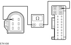
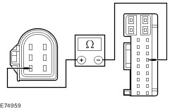
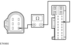
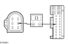
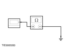
| | | Is the resistance less than 5 ohms? Yes No REPAIR circuit CBB34B (VT/BN) or circuit CRD35A (YE/GY). TEST the system for normal operation. | | D20: CHECK FOR CONTINUITY BETWEEN THE HEATED WINDSHIELD GLASS RELAY AND THE CENTRAL JUNCTION BOX (CJB) | | | 1 Disconnect CJB C1BP02-A. | | | 2 Measure the resistance between the CJB C1BP02-A pin 30, circuit CRD01A (VT/OG), harness side and the heated windshield glass relay R6 pin 2, circuit CRD01A (VT/OG), harness side. | | | Is the resistance less than 5 ohms? Yes CARRY OUT the CJB self-test. REFER to WDS. CARRY OUT the Heated Windshield Glass Relay component test. REFER to the Wiring Diagrams. No REPAIR circuit CRD01A (VT/OG). TEST the system for normal operation. | | PINPOINT TEST E : THE DEFROST SYSTEM WILL NOT SHUT OFF AUTOMATICALLY | | TEST CONDITIONS | DETAILS/RESULTS/ACTIONS | | E1: CHECK FOR CONTINUITY BETWEEN THE HEATED WINDSHIELD GLASS RELAY AND GROUND | NOTE:Use a digital multimeter for all electrical measurements. | | | 1 Disconnect CJB C1BP02-C. | | | 2 Disconnect Heated Windshield Glass Relay R6. | | | 3 Measure the resistance between the heated windshield glass relay R6 pin 2, circuit CRD01A (VT/OG), harness side and ground. | | | Is the resistance less than 5 ohms? Yes REPAIR circuit CRD01A (VT/OG). TEST the system for normal operation. No | | E2: CHECK THE HEATED WINDSHIELD GLASS RELAY CIRCUIT FOR A SHORT TO POWER | | | 1 Ignition switch in position II. | | | 2 Measure the voltage between the heated windshield glass relay R6 pin 5, harness side and ground. | | | Is the voltage greater than 10 volts? Yes REPAIR circuit CBB34B (VT/BN) or circuit CBB35A (YE/GY). TEST the system for normal operation. No | | E3: CHECK FOR CONTINUITY BETWEEN THE HEATED REAR WINDOW RELAY AND GROUND | | | 1 Ignition switch in position 0. | | | 2 Disconnect Heated Rear Window Relay RA2. | | | 3 Measure the resistance between the heated rear window relay RA2 pin 2, circuit CRD02A (BN/BU), harness side and ground. | | | Is the resistance less than 5 ohms? Yes REPAIR circuit CRD02A (BN/BU). TEST the system for normal operation. No | | E4: CHECK THE HEATED REAR WINDOW RELAY CIRCUIT FOR A SHORT TO POWER | | | 1 Ignition switch in position II. | | | 2 Measure the voltage between the heated rear window relay RA2 pin 5, circuit CRD06B (BN/YE), harness side and ground. | | | Is the voltage greater than 10 volts? Yes REPAIR circuit CRD06B (BN/YE). TEST the system for normal operation. No VERIFY the customer concern. | Component Tests Heated Rear Window Grid Wire Test - Using a bright lamp inside the vehicle, visually inspect the grid wire from the outside. A broken grid conductor line will appear as a brown spot.
- Run the engine at idle. Set the heated rear window switch and lights to ON. The heated rear window indicator light should illuminate.
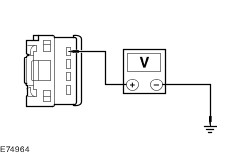
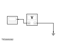
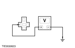
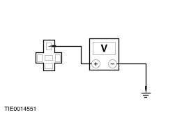
- Working inside the vehicle with a multimeter, contact the broad red/brown strips on the heated rear window positive lead to battery side and negative lead to ground side. The meter should read 10-13 volts. A lower voltage reading indicates a loose heated rear window ground wire connection at the heated rear window ground wire screw.
- Contact a ground point with the negative lead of the multimeter. The voltage reading should not change.
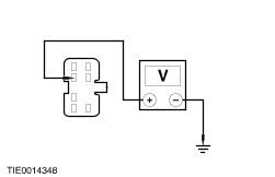
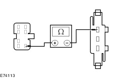
- With the negative lead of the multimeter grounded, touch each grid line of the heated rear window at its pinpoint with the positive lead. A reading of approximately six volts indicates that the line is OK. A reading of zero volts indicates that the line is broken between the midpoint and the battery side of the grid line. A reading of 12 volts indicates that the circuit is broken between the midpoint of the grid line and ground.
- INSTALL a new heated rear window glass.
REFER to: Liftgate Window Glass (501-11 Glass, Frames and Mechanisms, Removal and Installation).
|