| Removal and Installation Measurement or alignment angle system | | -
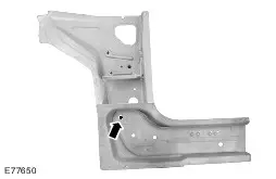
Replacement parts - Rocker panel reinforcement
| Removal | | -
General Notes - The apron panel reinforcement needs to be removed before the repairs can be started.
- Required removal operations: A-pillar trim panel, rocker panel trim and driver or passenger seat.
- Reposition the carpeting and the wiring harness away from the working area.
| NOTE:Due to the locations of inner reinforcements and NVH elements, it is very important that the dimensions quoted for the separating cuts on the outer A-pillar and on the rocker panel are accurately met. | | -
A-Pillar outer - Mill out the spot welds (two panel thicknesses).
| | | -
A-Pillar outer - Grind out the MIG brazed joints.
- Heat the areas (approx. 170° C) and detach the NVH elements.
| | | -
A-pillar reinforcement - Mill out the spot welds.
- Heat the areas (approx. 170° C) and detach the NVH elements.
| | | -
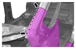
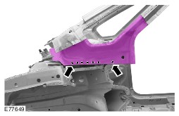
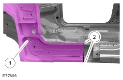
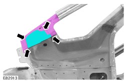
Rocker panel reinforcement - Cut location.
- Mill out the spot welds.
| | | -
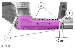
A-pillar inner panel - Cut location.
- Mill out the spot welds (two panel thicknesses).
| | | -
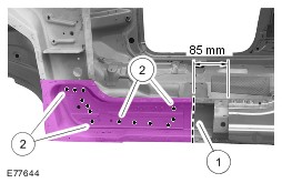
A-pillar inner panel - Mill out the spot welds.
- Grind out the spot welds.
| | | -
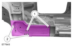
A-pillar inner panel - Mill out the spot welds (two panel thicknesses).
- Grind out the spot welds.
| | | -
A-pillar, inner panel (inside view) | | | -
A-pillar, inner panel (inside view) - Heat the area (approx. 170° C) and release the NVH element.
| Installation NOTE:Before resistance spot welding of body panels with a total panel thickness of 3 mm and greater, the welding equipment instructions contained in sub-section 501-25 must be followed. | | -
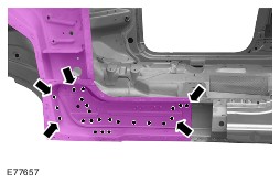
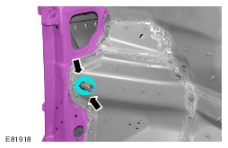
A-pillar inner panel - Drill out the holes for puddle welding (10 mm diameter).
| | | -
A-pillar inner panel - Drill a hole for puddle welding (10 mm diameter).
| | | -
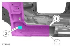
A-pillar inner panel - Puddle weld.
- Continuous MIG weld seam.
| | | -
A-pillar inner panel - Surface grind the MIG weld seams in the area of the welded flange.
NOTE:Once the A-pillar reinforcement and the A-pillar outer panel have been installed this area is no longer accessible. - Apply self-adhesive sealing strip.
| | | -
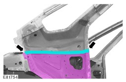
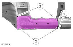
NOTE:Only tack-weld the rocker panel reinforcement at the top and bottom. The final welded joint is made when the rocker panel is installed. Rocker panel reinforcement - Continuous MIG weld seam.
- Resistance spot welding (tack-weld).
| | | -
WARNING:The A-pillar reinforcement is covered with a hot-dip aluminized coating on its entire surface. This coating needs to be fully ground off on the MIG welding flanges on the front using a fibre grinding disc. Any contamination due to parts of the coating in the welding bath will weaken the welded joint. A-pillar reinforcement | | | -
A-pillar reinforcement - Drill holes for puddle welding (10 mm diameter).
| | | -
NOTE:Working from the inside, insert the NVH element at the A-pillar reinforcement into the mounting tube for the instrument panel bracket. A-pillar, inner panel (inside view) - Apply PU glass adhesive to the NVH element.
| | | -
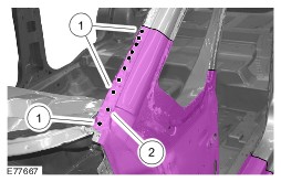
NOTE:The PU window adhesive acts as noise insulation in the area of position 1. A-pillar reinforcement - Apply PU window adhesive to the inside of the A-pillar.
- Apply PU glass adhesive to the NVH element.
- Puddle weld.
| | | -
NOTE:Only tack-weld A-pillar reinforcement. The final welded joint is made when the outer A-pillar is installed. A-pillar reinforcement - Resistance spot welding (tack-weld).
| | | -
NOTE:The MIG spot welds need to be surface ground so that the outer A-pillar fits correctly. A-pillar reinforcement - Surface grind the MIG spot welds.
| | | -
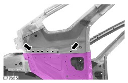
A-Pillar outer - Drill holes for puddle welding (10 mm diameter).
| - The factory-installed MIG brazed joints must be replaced by MIG welds in a different position if a repair is performed.
- These MIG welds must not be carried out on or in the immediate vicinity of existing MIG brazed seams as even the smallest amount of brazing solder can result in a reduction in the strength of the weld seam.
| | -
NOTE:For the reasons described above, when preparing the outer A-panel the existing openings need to be enlarged by 10 mm (see illustration E77653). A-Pillar outer - Mill out the openings with a spherical cutter.
| | | -
NOTE:The PU window adhesive acts as noise insulation in the area of positions 2. A-Pillar outer - Apply PU glass adhesive to the NVH element.
- Apply PU window adhesive to the inside of the A-pillar.
- Continuous MIG weld seam.
| | | -
A-Pillar outer - Resistance spot weld.
- Puddle weld.
| | |