
Seats
- Make
- Ford
- Model
- Taurus Factory Service Manual
- Year
- 2007
- Section
- 501-10 Seating › Diagnosis and testing › Seats
Seats
 |
Restraint System Diagnostic Tool (2 required)
418-133 (40-009) |
 |
Restraint System Diagnostic Tool (2 required)
418-F395 (014-R1079) |
Restraint System Diagnostic Tool Warning
WARNING: This tool is for restraint system service only. Remove from vehicle prior to road use. Failure to remove could result in injury and possible violation of vehicle safety standards.
Inspection and Verification
- Verify the customer concern by operating the power seat.
- Visually inspect for obvious signs of mechanical and electrical damage.
| Mechanical | Electrical |
|---|---|
|
|
- If a obvious cause for an observed or reported concern is found, correct the cause (if possible) before proceeding to the next step.
- If the cause is not visually evident, verify the symptom and GO to Symptom Chart.
Symptom Chart
| Condition | Possible Sources | Action |
|---|---|---|
|
|
|
|
|
|
|
|
|
|
|
|
|
|
|
|
|
|
|
|
|
|
|
|
|
|
|
|
|
|
|
|
Pinpoint Tests
WARNING: Always wear safety glasses when repairing an air bag supplemental restraint system (SRS) vehicle and when handling an airbag module. This will reduce the risk of injury in the event of an accidental deployment.
WARNING: Never probe the connectors on the air bag module. Doing so can result in air bag deployment, which can result in personal injury.
Refer to Inspection and Verification and the Symptom Chart for direction to the appropriate Pinpoint Test.
Pinpoint Test A: The Power Seat Is Inoperative — Driver Seat
Refer to Wiring Diagrams Cell 120, Power Seats for schematic and connector information.
Refer to Wiring Diagrams Cell 149, Component Testing for schematic and connector information.
Normal Operation
The seat control switch is powered by battery voltage to circuit 490 (RD) and is supplied ground on circuit 57 (BK). The seat control switch applies battery power and ground directly to one of 3 bi-directional seat track motors, respectively, to move the seat. Toggling the seat control switch to the opposite position reverses the voltage polarity applied to the respective seat motor and moves the seat in the opposite direction.
Possible Causes
An inoperative driver power seat can be caused by:
- fuse.
- circuit 490 (RD) open.
- circuit 57 (BK) open.
- a faulty seat control switch.
PINPOINT TEST A: THE POWER SEAT IS INOPERATIVE — DRIVER SEAT
| Test Step | Result / Action to Take |
|---|---|
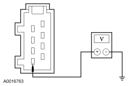
| A1 CHECK FOR VOLTAGE AT THE SEAT CONTROL SWITCH | |
|
Yes GO to A2. No VERIFY the smart junction box (SJB) fuse 10 (30A) is OK. If OK, REPAIR circuit 490 (RD). TEST the system for normal operation. DISCONNECT the battery ground cable. DISCONNECT the restraint system diagnostic tool from the driver seat safety belt buckle pretensioner electrical connector. CONNECT the driver seat safety belt buckle pretensioner electrical connector. For vehicles equipped with seat side air bags, DISCONNECT the restraint system diagnostic tool from driver seat side air bag module C314. CONNECT driver seat side air bag module C314. For all vehicles, REPOWER the supplemental restraint system (SRS). REFER to Section 501-20B. |
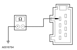
| A2 CHECK CIRCUIT 57 (BK) FOR AN OPEN | |
|
Yes GO to A3. No REPAIR circuit 57 (BK). TEST the system for normal operation. DISCONNECT the battery ground cable. DISCONNECT the restraint system diagnostic tool from the driver seat safety belt buckle pretensioner electrical connector. CONNECT the driver seat safety belt buckle pretensioner electrical connector. For vehicles equipped with seat side air bags, DISCONNECT the restraint system diagnostic tool from driver seat side air bag module C314. CONNECT driver seat side air bag module C314. For all vehicles, REPOWER the supplemental restraint system (SRS). REFER to Section 501-20B. |
| A3 CHECK THE SEAT CONTROL SWITCH | |
|
Yes CHECK for an obstructed or binding seat track. If no obstruction or binding is found, INSTALL a new seat track. REFER to Seat Track — Power in this section. TEST the system for normal operation. DISCONNECT the battery ground cable. DISCONNECT the restraint system diagnostic tool from the driver seat safety belt buckle pretensioner electrical connector. CONNECT the driver seat safety belt buckle pretensioner electrical connector. For vehicles equipped with seat side air bags, DISCONNECT the restraint system diagnostic tool from driver seat side air bag module C314. CONNECT driver seat side air bag module C314. For all vehicles, REPOWER the supplemental restraint system (SRS). REFER to Section 501-20B. No INSTALL a new seat control switch. TEST the system for normal operation. For all vehicles, DISCONNECT the battery ground cable. DISCONNECT the restraint system diagnostic tool from the driver seat safety belt buckle pretensioner electrical connector. CONNECT the driver seat safety belt buckle pretensioner electrical connector. For vehicles equipped with seat side air bags, DISCONNECT the restraint system diagnostic tool from driver seat side air bag module C314. CONNECT driver seat side air bag module C314. For all vehicles, REPOWER the supplemental restraint system (SRS). REFER to Section 501-20B. |
Pinpoint Test B: The Power Seat Is Inoperative — Passenger Seat
Refer to Wiring Diagrams Cell 120, Power Seats for schematic and connector information.
Refer to Wiring Diagrams Cell 149, Component Testing for schematic and connector information.
Normal Operation
The seat control switch is powered by battery voltage to circuit 490 (RD) and is supplied ground on circuit 57 (BK). The seat control switch applies battery power and ground directly to one of 3 bi-directional seat track motors, respectively, to move the seat. Toggling the seat control switch to the opposite position reverses the voltage polarity applied to the respective seat motor and moves the seat in the opposite direction.
Possible Causes
An inoperative passenger power seat can be caused by:
- fuse.
- circuit 490 (RD) open.
- circuit 57 (BK) open.
- a faulty seat control switch.
PINPOINT TEST B: THE POWER SEAT IS INOPERATIVE — PASSENGER SEAT
| Test Step | Result / Action to Take |
|---|---|
| B1 CHECK FOR VOLTAGE AT THE SEAT CONTROL SWITCH | |
|
Yes GO to B2. No VERIFY the smart junction box (SJB) fuse 10 (30A) is OK. If OK, REPAIR circuit 490 (RD). TEST the system for normal operation. DISCONNECT the battery ground cable. DISCONNECT the restraint system diagnostic tool from the passenger seat safety belt buckle pretensioner electrical connector. CONNECT the passenger seat safety belt buckle pretensioner electrical connector. For vehicles equipped with seat side air bags, DISCONNECT the restraint system diagnostic tool from passenger seat side air bag module C316. CONNECT passenger seat side air bag module C316. For all vehicles, REPOWER the supplemental restraint system (SRS). REFER to Section 501-20B. |
| B2 CHECK CIRCUIT 57 (BK) FOR AN OPEN | |
|
Yes GO to B3. No REPAIR circuit 57 (BK). TEST the system for normal operation. DISCONNECT the battery ground cable. DISCONNECT the restraint system diagnostic tool from the passenger seat safety belt buckle pretensioner electrical connector. CONNECT the passenger seat safety belt buckle pretensioner electrical connector. For vehicles equipped with seat side air bags, DISCONNECT the restraint system diagnostic tool from passenger seat side air bag module C316. CONNECT passenger seat side air bag module C316. For all vehicles, REPOWER the supplemental restraint system (SRS). REFER to Section 501-20B. |
| B3 CHECK THE SEAT CONTROL SWITCH | |
|
Yes CHECK for an obstructed or binding seat track. If no obstruction or binding is found, INSTALL a new seat track. REFER to Seat Track — Power in this section. TEST the system for normal operation. DISCONNECT the battery ground cable. DISCONNECT the restraint system diagnostic tool from the passenger seat safety belt buckle pretensioner electrical connector. CONNECT the passenger seat safety belt buckle pretensioner electrical connector. For vehicles equipped with seat side air bags, DISCONNECT the restraint system diagnostic tool from passenger seat side air bag module C316. CONNECT passenger seat side air bag module C316. For all vehicles, REPOWER the supplemental restraint system (SRS). REFER to Section 501-20B. No INSTALL a new seat control switch. TEST the system for normal operation. DISCONNECT the battery ground cable. DISCONNECT the restraint system diagnostic tool from the passenger seat safety belt buckle pretensioner electrical connector. CONNECT the passenger seat safety belt buckle pretensioner electrical connector. For vehicles equipped with seat side air bags, DISCONNECT the restraint system diagnostic tool from passenger seat side air bag module C316. CONNECT passenger seat side air bag module C316. For all vehicles, REPOWER the supplemental restraint system (SRS). REFER to Section 501-20B. |
Pinpoint Test C: The Power Seat Moves But Is Noisy
Normal Operation
The power seat should move quietly during operation. Some noise is acceptable.
Possible Causes
A noisy power seat can be caused by:
- a misaligned seat track.
- a faulty seat track component.
- an object obstructing seat movement.
PINPOINT TEST C: THE POWER SEAT MOVES BUT IS NOISY
| Test Step | Result / Action to Take |
|---|---|
| C1 CHECK THE TRACK ALIGNMENT | |
|
Yes ALIGN the track to the seat and the floor. TEST the system for normal operation. DISCONNECT the battery ground cable. DISCONNECT the restraint system diagnostic tool from the driver or passenger seat safety belt buckle pretensioner electrical connector. CONNECT the driver or passenger seat safety belt buckle pretensioner electrical connector. For vehicles equipped with seat side air bags, DISCONNECT the restraint system diagnostic tool from driver seat side air bag module C314 or passenger seat side air bag module C316. CONNECT driver seat side air bag module C314 or passenger seat side air bag module C316. For all vehicles, REPOWER the supplemental restraint system (SRS). REFER to Section 501-20B. No INSTALL a new power seat track. REFER to Seat Track — Power in this section. TEST the system for normal operation. DISCONNECT the battery ground cable. DISCONNECT the restraint system diagnostic tool from the driver or passenger seat safety belt buckle pretensioner electrical connector. CONNECT the driver or passenger seat safety belt buckle pretensioner electrical connector. For vehicles equipped with seat side air bags, DISCONNECT the restraint system diagnostic tool from driver seat side air bag module C314 or passenger seat side air bag module C316. CONNECT driver seat side air bag module C314 or passenger seat side air bag module C316. For all vehicles, REPOWER the supplemental restraint system (SRS). REFER to Section 501-20B. |
Pinpoint Test D: The Power Seat Moves But Is Loose
Normal Operation
The power seat movement should be smooth and the seat cushion should not rock during or after operation.
Possible Causes
A loose power seat can be caused by:
- loose seat fastening hardware.
- a faulty seat track component.
PINPOINT TEST D: THE POWER SEAT MOVES BUT IS LOOSE
| Test Step | Result / Action to Take |
|---|---|
| D1 CHECK THE FASTENING HARDWARE | |
|
Yes TIGHTEN all fastening hardware to specification. TEST the system for normal operation. DISCONNECT the battery ground cable. DISCONNECT the restraint system diagnostic tool from the driver or passenger seat safety belt buckle pretensioner electrical connector. CONNECT the driver or passenger seat safety belt buckle pretensioner electrical connector. For vehicles equipped with seat side air bags, DISCONNECT the restraint system diagnostic tool from driver seat side air bag module C314 or passenger seat side air bag module C316. CONNECT driver seat side air bag module C314 or passenger seat side air bag module C316. For all vehicles, REPOWER the supplemental restraint system (SRS). REFER to Section 501-20B. No INSTALL a new seat track. REFER to Seat Track — Power in this section. TEST the system for normal operation. DISCONNECT the battery ground cable. DISCONNECT the restraint system diagnostic tool from the driver or passenger seat safety belt buckle pretensioner electrical connector. CONNECT the driver or passenger seat safety belt buckle pretensioner electrical connector. For vehicles equipped with seat side air bags, DISCONNECT the restraint system diagnostic tool from driver seat side air bag module C314 or passenger seat side air bag module C316. CONNECT driver seat side air bag module C314 or passenger seat side air bag module C316. For all vehicles, REPOWER the supplemental restraint system (SRS). REFER to Section 501-20B. |
Pinpoint Test E: The Power Seat Does Not Make Full Travel
Normal Operation
The driver power seat should travel fully horizontal (FORWARD/REARWARD) and vertical (front UP/DOWN and rear UP/DOWN). The passenger power seat should travel fully horizontal (FORWARD/REARWARD).
Possible Causes
A power seat that does not make full travel can be caused by:
- an obstructed seat track.
- a faulty seat track component.
PINPOINT TEST E: THE POWER SEAT DOES NOT MAKE FULL TRAVEL
| Test Step | Result / Action to Take |
|---|---|
| E1 CHECK FOR AN OBSTRUCTION IN THE SEAT TRACK | |
|
Yes REMOVE the obstruction(s) and grease the track(s). TEST the system for normal operation. DISCONNECT the battery ground cable. DISCONNECT the restraint system diagnostic tool from the driver or passenger seat safety belt buckle pretensioner electrical connector. CONNECT the driver or passenger seat safety belt buckle pretensioner electrical connector. For vehicles equipped with seat side air bags, DISCONNECT the restraint system diagnostic tool from driver seat side air bag module C314 or passenger seat side air bag module C316. CONNECT driver seat side air bag module C314 or passenger seat side air bag module C316. For all vehicles, REPOWER the supplemental restraint system (SRS). REFER to Section 501-20B. No INSTALL a new seat track. REFER to Seat Track — Power in this section. TEST the system for normal operation. DISCONNECT the battery ground cable. DISCONNECT the restraint system diagnostic tool from the driver or passenger seat safety belt buckle pretensioner electrical connector. CONNECT the driver or passenger seat safety belt buckle pretensioner electrical connector. For vehicles equipped with seat side air bags, DISCONNECT the restraint system diagnostic tool from driver seat side air bag module C314 or passenger seat side air bag module C316. CONNECT driver seat side air bag module C314 or passenger seat side air bag module C316. For all vehicles, REPOWER the supplemental restraint system (SRS). REFER to Section 501-20B. |
Pinpoint Test F: The Power Seat Does Not Move Horizontally — Driver Seat
Refer to Wiring Diagrams Cell 120, Power Seats for schematic and connector information.
Normal Operation
The seat control switch is powered by battery voltage to circuit 490 (RD) and is supplied ground on circuit 57 (BK). When either the FORWARD or REARWARD position is selected on the seat control switch, power and ground is applied to circuits 980 (YE/WH) and 981 (RD/WH) powering the horizontal motor to move the seat FORWARD or REARWARD. When the opposite switch position is selected, the seat control switch reverses the voltage polarity to the horizontal motor to move the seat in the opposite direction.
Possible Causes
An inoperative driver power seat can be caused by:
- circuit 980 (YE/WH) open or short to ground.
- circuit 981 (RD/WH) open or short to ground.
- a faulty seat control switch.
- a faulty seat track.
PINPOINT TEST F: THE POWER SEAT DOES NOT MOVE HORIZONTALLY — DRIVER SEAT
| Test Step | Result / Action to Take |
|---|---|
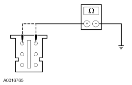
| F1 CHECK MOTOR SUPPLY CIRCUITS 980 (YE/WH) AND 981 (RD/WH) FOR A SHORT TO GROUND | |
|
Yes GO to F3. No GO to F2. |
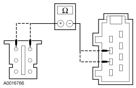
| F2 CHECK CIRCUITS 981 (RD/WH) AND 980 (YE/WH) FOR AN OPEN | |
|
Yes INSTALL a new seat control switch. TEST the system for normal operation. DISCONNECT the battery ground cable. DISCONNECT the restraint system diagnostic tool from the driver seat safety belt buckle pretensioner electrical connector. CONNECT the driver seat safety belt buckle pretensioner electrical connector. For vehicles equipped with seat side air bags, DISCONNECT the restraint system diagnostic tool from driver seat side air bag module C314. CONNECT driver seat side air bag module C314. For all vehicles, REPOWER the supplemental restraint system (SRS). REFER to Section 501-20B. No REPAIR the affected circuit(s). TEST the system for normal operation. DISCONNECT the battery ground cable. DISCONNECT the restraint system diagnostic tool from the driver seat safety belt buckle pretensioner electrical connector. CONNECT the driver seat safety belt buckle pretensioner electrical connector. For vehicles equipped with seat side air bags, DISCONNECT the restraint system diagnostic tool from driver seat side air bag module C314. CONNECT driver seat side air bag module C314. For all vehicles, REPOWER the supplemental restraint system (SRS). REFER to Section 501-20B. |
| F3 CHECK CIRCUIT 981 (RD/WH) FOR VOLTAGE TO THE SEAT TRACK MOTOR ASSEMBLY | |
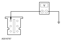
|
Yes GO to F4. No INSTALL a new seat control switch. TEST the system for normal operation. DISCONNECT the battery ground cable. DISCONNECT the restraint system diagnostic tool from the driver seat safety belt buckle pretensioner electrical connector. CONNECT the driver seat safety belt buckle pretensioner electrical connector. For vehicles equipped with seat side air bags, DISCONNECT the restraint system diagnostic tool from driver seat side air bag module C314. CONNECT driver seat side air bag module C314. For all vehicles, REPOWER the supplemental restraint system (SRS). REFER to Section 501-20B. |
| F4 CHECK CIRCUIT 980 (YE/WH) FOR VOLTAGE TO THE SEAT TRACK MOTOR ASSEMBLY | |
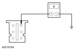
|
Yes INSTALL a new seat track. REFER to Seat Track — Power in this section. TEST the system for normal operation. DISCONNECT the battery ground cable. DISCONNECT the restraint system diagnostic tool from the driver seat safety belt buckle pretensioner electrical connector. CONNECT the driver seat safety belt buckle pretensioner electrical connector. For vehicles equipped with seat side air bags, DISCONNECT the restraint system diagnostic tool from driver seat side air bag module C314. CONNECT driver seat side air bag module C314. For all vehicles, REPOWER the supplemental restraint system (SRS). REFER to Section 501-20B. No INSTALL a new seat control switch. TEST the system for normal operation. DISCONNECT the battery ground cable. DISCONNECT the restraint system diagnostic tool from the driver seat safety belt buckle pretensioner electrical connector. CONNECT the driver seat safety belt buckle pretensioner electrical connector. For vehicles equipped with seat side air bags, DISCONNECT the restraint system diagnostic tool from driver seat side air bag module C314. CONNECT driver seat side air bag module C314. For all vehicles, REPOWER the supplemental restraint system (SRS). REFER to Section 501-20B. |
Pinpoint Test G: The Power Seat Does Not Move Horizontally — Passenger Seat
Refer to Wiring Diagrams Cell 120, Power Seats for schematic and connector information.
Normal Operation
The seat control switch is powered by battery voltage to circuit 490 (RD) and is supplied ground on circuit 57 (BK). When either the FORWARD or REARWARD position is selected on the seat control switch, power and ground is applied to circuits 980 (YE/WH) and 981 (RD/WH) powering the horizontal motor to move the seat FORWARD or REARWARD. When the opposite switch position is selected, the seat control switch reverses the voltage polarity to the horizontal motor to move the seat in the opposite direction.
Possible Causes
An inoperative passenger power seat can be caused by:
- circuit 980 (YE/WH) open or short to ground.
- circuit 981 (RD/WH) open or short to ground.
- a faulty seat control switch.
- a faulty seat track.
PINPOINT TEST G: THE POWER SEAT DOES NOT MOVE HORIZONTALLY — PASSENGER SEAT
| Test Step | Result / Action to Take |
|---|---|
| G1 CHECK MOTOR SUPPLY CIRCUITS 980 (YE/WH) AND 981 (RD/WH) FOR A SHORT TO GROUND | |
|
Yes GO to G3. No GO to G2. |
| G2 CHECK CIRCUITS 981 (RD/WH) AND 980 (YE/WH) FOR OPEN | |
|
Yes INSTALL a new seat control switch. TEST the system for normal operation. DISCONNECT the battery ground cable. DISCONNECT the restraint system diagnostic tool from the passenger seat safety belt buckle pretensioner electrical connector. CONNECT the passenger seat safety belt buckle pretensioner electrical connector. For vehicles equipped with seat side air bags, DISCONNECT the restraint system diagnostic tool from passenger seat side air bag module C316. CONNECT passenger seat side air bag module C316. For all vehicles, REPOWER the supplemental restraint system (SRS). REFER to Section 501-20B. No REPAIR the affected circuit(s). TEST the system for normal operation. DISCONNECT the battery ground cable. DISCONNECT the restraint system diagnostic tool from the passenger seat safety belt buckle pretensioner electrical connector. CONNECT the passenger seat safety belt buckle pretensioner electrical connector. For vehicles equipped with seat side air bags, DISCONNECT the restraint system diagnostic tool from passenger seat side air bag module C316. CONNECT passenger seat side air bag module C316. For all vehicles, REPOWER the supplemental restraint system (SRS). REFER to Section 501-20B. |
| G3 CHECK CIRCUIT 981 (RD/WH) FOR VOLTAGE TO THE SEAT TRACK MOTOR ASSEMBLY | |
|
Yes GO to G4. No INSTALL a new seat control switch. TEST the system for normal operation. DISCONNECT the battery ground cable. DISCONNECT the restraint system diagnostic tool from the passenger seat safety belt buckle pretensioner electrical connector. CONNECT the passenger seat safety belt buckle pretensioner electrical connector. For vehicles equipped with seat side air bags, DISCONNECT the restraint system diagnostic tool from passenger seat side air bag module C316. CONNECT passenger seat side air bag module C316. For all vehicles, REPOWER the supplemental restraint system (SRS). REFER to Section 501-20B. |
| G4 CHECK CIRCUIT 980 (YE/WH) FOR VOLTAGE TO THE SEAT TRACK MOTOR ASSEMBLY | |
|
Yes INSTALL a new seat track. REFER to Seat Track — Power in this section. TEST the system for normal operation. DISCONNECT the battery ground cable. DISCONNECT the restraint system diagnostic tool from the passenger seat safety belt buckle pretensioner electrical connector. CONNECT the passenger seat safety belt buckle pretensioner electrical connector. For vehicles equipped with seat side air bags, DISCONNECT the restraint system diagnostic tool from passenger seat side air bag module C316. CONNECT passenger seat side air bag module C316. For all vehicles, REPOWER the supplemental restraint system (SRS). REFER to Section 501-20B. No INSTALL a new seat control switch. TEST the system for normal operation. DISCONNECT the battery ground cable. DISCONNECT the restraint system diagnostic tool from the passenger seat safety belt buckle pretensioner electrical connector. CONNECT the passenger seat safety belt buckle pretensioner electrical connector. For vehicles equipped with seat side air bags, DISCONNECT the restraint system diagnostic tool from passenger seat side air bag module C316. CONNECT passenger seat side air bag module C316. For all vehicles, REPOWER the supplemental restraint system (SRS). REFER to Section 501-20B. |
Pinpoint Test H: The Power Seat Does Not Move Vertically — Driver Seat, Front Height
Refer to Wiring Diagrams Cell 120, Power Seats for schematic and connector information.
Normal Operation
The seat control switch is powered by battery voltage to circuit 490 (RD) and is supplied ground on circuit 57 (BK). When either the FRONT UP or FRONT DOWN position is selected on the seat control switch, power and ground is applied to circuits 979 (RD/LB) and 990 (YE/LB) powering the front height motor to move the seat UP or DOWN. When the opposite switch position is selected, the seat control switch reverses the voltage polarity to the front height motor to move the seat in the opposite direction.
Possible Causes
A driver power seat front height motor that does not move the seat vertically can be caused by:
- circuit 979 (RD/LB) open or short to ground.
- circuit 990 (YE/LB) open or short to ground.
- a faulty seat control switch.
- a faulty seat track.
PINPOINT TEST H: THE POWER SEAT DOES NOT MOVE VERTICALLY — DRIVER SEAT, FRONT HEIGHT
| Test Step | Result / Action to Take |
|---|---|
| H1 CHECK MOTOR SUPPLY CIRCUITS 979 (RD/LB) AND 990 (YE/LB) FOR A SHORT TO GROUND | |
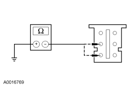
|
Yes GO to H3. No GO to H2. |
| H2 CHECK CIRCUITS 979 (RD/LB) AND 990 (YE/LB) FOR OPEN | |
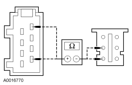
|
Yes INSTALL a new seat control switch. TEST the system for normal operation. DISCONNECT the battery ground cable. DISCONNECT the restraint system diagnostic tool from the driver seat safety belt buckle pretensioner electrical connector. CONNECT the driver seat safety belt buckle pretensioner electrical connector. For vehicles equipped with seat side air bags, DISCONNECT the restraint system diagnostic tool from driver seat side air bag module C314. CONNECT driver seat side air bag module C314. For all vehicles, REPOWER the supplemental restraint system (SRS). REFER to Section 501-20B. No REPAIR the affected circuit(s). TEST the system for normal operation. DISCONNECT the battery ground cable. DISCONNECT the restraint system diagnostic tool from the driver seat safety belt buckle pretensioner electrical connector. CONNECT the driver seat safety belt buckle pretensioner electrical connector. For vehicles equipped with seat side air bags, DISCONNECT the restraint system diagnostic tool from driver seat side air bag module C314. CONNECT driver seat side air bag module C314. For all vehicles, REPOWER the supplemental restraint system (SRS). REFER to Section 501-20B. |
| H3 CHECK CIRCUIT 979 (RD/LB) FOR VOLTAGE TO THE SEAT TRACK MOTOR ASSEMBLY | |
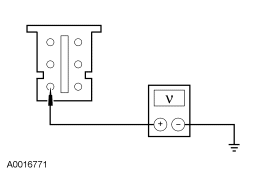
|
Yes GO to H4. No INSTALL a new seat control switch. TEST the system for normal operation. DISCONNECT the battery ground cable. DISCONNECT the restraint system diagnostic tool from the driver seat safety belt buckle pretensioner electrical connector. CONNECT the driver seat safety belt buckle pretensioner electrical connector. For vehicles equipped with seat side air bags, DISCONNECT the restraint system diagnostic tool from driver seat side air bag module C314. CONNECT driver seat side air bag module C314. For all vehicles, REPOWER the supplemental restraint system (SRS). REFER to Section 501-20B. |
| H4 CHECK CIRCUIT 990 (YE/LB) FOR VOLTAGE TO THE SEAT TRACK MOTOR ASSEMBLY | |
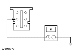
|
Yes INSTALL a new seat track. REFER to Seat Track — Power in this section. TEST the system for normal operation. DISCONNECT the battery ground cable. DISCONNECT the restraint system diagnostic tool from the driver seat safety belt buckle pretensioner electrical connector. CONNECT the driver seat safety belt buckle pretensioner electrical connector. For vehicles equipped with seat side air bags, DISCONNECT the restraint system diagnostic tool from driver seat side air bag module C314. CONNECT driver seat side air bag module C314. For all vehicles, REPOWER the supplemental restraint system (SRS). REFER to Section 501-20B. No INSTALL a new seat control switch. TEST the system for normal operation. DISCONNECT the battery ground cable. DISCONNECT the restraint system diagnostic tool from the driver seat safety belt buckle pretensioner electrical connector. CONNECT the driver seat safety belt buckle pretensioner electrical connector. For vehicles equipped with seat side air bags, DISCONNECT the restraint system diagnostic tool from driver seat side air bag module C314. CONNECT driver seat side air bag module C314. For all vehicles, REPOWER the supplemental restraint system (SRS). REFER to Section 501-20B. |
Pinpoint Test I: The Power Seat Does Not Move Vertically — Passenger Seat, Front Height
Refer to Wiring Diagrams Cell 120, Power Seats for schematic and connector information.
Normal Operation
The seat control switch is powered by battery voltage to circuit 490 (RD) and is supplied ground on circuit 57 (BK). When either the FRONT UP or FRONT DOWN position is selected on the seat control switch, power and ground is applied to circuits 979 (RD/LB) and 990 (YE/LB) powering the front height motor to move the seat UP or DOWN. When the opposite switch position is selected, the seat control switch reverses the voltage polarity to the front height motor to move the seat in the opposite direction.
Possible Causes
A passenger power seat front height motor that does not move the seat vertically can be caused by:
- circuit 979 (RD/LB) open or short to ground.
- circuit 990 (YE/LB) open or short to ground.
- a faulty seat control switch.
- a faulty seat track.
PINPOINT TEST I: THE POWER SEAT DOES NOT MOVE VERTICALLY — PASSENGER SEAT, FRONT HEIGHT
| Test Step | Result / Action to Take |
|---|---|
| I1 CHECK MOTOR SUPPLY CIRCUITS 979 (RD/LB) AND 990 (YE/LB) FOR A SHORT TO GROUND | |
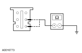
|
Yes GO to I3. No GO to I2. |
| I2 CHECK CIRCUITS 979 (RD/LB) AND 990 (YE/LB) FOR AN OPEN | |
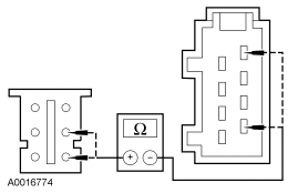
|
Yes INSTALL a new seat control switch. TEST the system for normal operation. DISCONNECT the battery ground cable. DISCONNECT the restraint system diagnostic tool from the passenger seat safety belt buckle pretensioner electrical connector. CONNECT the passenger seat safety belt buckle pretensioner electrical connector. For vehicles equipped with seat side air bags, DISCONNECT the restraint system diagnostic tool from passenger seat side air bag module C316. CONNECT passenger seat side air bag module C316. For all vehicles, REPOWER the supplemental restraint system (SRS). REFER to Section 501-20B. No REPAIR the affected circuit(s). TEST the system for normal operation. DISCONNECT the battery ground cable. DISCONNECT the restraint system diagnostic tool from the passenger seat safety belt buckle pretensioner electrical connector. CONNECT the passenger seat safety belt buckle pretensioner electrical connector. For vehicles equipped with seat side air bags, DISCONNECT the restraint system diagnostic tool from passenger seat side air bag module C316. CONNECT passenger seat side air bag module C316. For all vehicles, REPOWER the supplemental restraint system (SRS). REFER to Section 501-20B. |
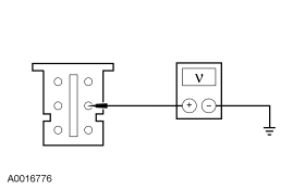
| I3 CHECK CIRCUIT 979 (RD/LB) FOR VOLTAGE TO THE SEAT TRACK MOTOR ASSEMBLY | |
|
Yes GO to I4. No INSTALL a new seat control switch. TEST the system for normal operation. DISCONNECT the battery ground cable. DISCONNECT the restraint system diagnostic tool from the passenger seat safety belt buckle pretensioner electrical connector. CONNECT the passenger seat safety belt buckle pretensioner electrical connector. For vehicles equipped with seat side air bags, DISCONNECT the restraint system diagnostic tool from passenger seat side air bag module C316. CONNECT passenger seat side air bag module C316. For all vehicles, REPOWER the supplemental restraint system (SRS). REFER to Section 501-20B. |
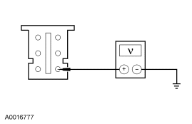
| I4 CHECK CIRCUIT 990 (YE/LB) FOR VOLTAGE TO THE SEAT TRACK MOTOR ASSEMBLY | |
|
Yes INSTALL a new seat track. REFER to Seat Track — Power in this section. TEST the system for normal operation. DISCONNECT the battery ground cable. DISCONNECT the restraint system diagnostic tool from the passenger seat safety belt buckle pretensioner electrical connector. CONNECT the passenger seat safety belt buckle pretensioner electrical connector. For vehicles equipped with seat side air bags, DISCONNECT the restraint system diagnostic tool from passenger seat side air bag module C316. CONNECT passenger seat side air bag module C316. For all vehicles, REPOWER the supplemental restraint system (SRS). REFER to Section 501-20B. No INSTALL a new seat control switch. TEST the system for normal operation. DISCONNECT the battery ground cable. DISCONNECT the restraint system diagnostic tool from the passenger seat safety belt buckle pretensioner electrical connector. CONNECT the passenger seat safety belt buckle pretensioner electrical connector. For vehicles equipped with seat side air bags, DISCONNECT the restraint system diagnostic tool from passenger seat side air bag module C316. CONNECT passenger seat side air bag module C316. For all vehicles, REPOWER the supplemental restraint system (SRS). REFER to Section 501-20B. |
Pinpoint Test J: The Power Seat Does Not Move Vertically — Driver Seat, Rear Height
Refer to Wiring Diagrams Cell 120, Power Seats for schematic and connector information.
Normal Operation
The seat control switch is powered by battery voltage to circuit 490 (RD) and is supplied ground on circuit 57 (BK). When either the REAR UP or REAR DOWN position is selected on the seat control switch, power and ground is applied to circuits 982 (YE/LG) and 983 (RD/LG) powering the rear height motor to move the seat UP or DOWN. When the opposite switch position is selected, the seat control switch reverses the voltage polarity to the rear height motor to move the seat in the opposite direction.
Possible Causes
A driver power seat rear height motor that does not move the seat vertically can be caused by:
- circuit 982 (YE/LG) open or short to ground.
- circuit 983 (RD/LG) open or short to ground.
- a faulty seat control switch.
- a faulty seat track.
PINPOINT TEST J: THE POWER SEAT DOES NOT MOVE VERTICALLY — DRIVER SEAT, REAR HEIGHT
| Test Step | Result / Action to Take |
|---|---|
| J1 CHECK MOTOR SUPPLY CIRCUITS 982 (YE/LG) AND 983 (RD/LG) FOR A SHORT TO GROUND | |
|
Yes GO to J3. No GO to J2. |
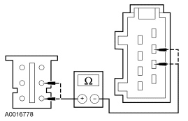
| J2 CHECK CIRCUITS 983 (RD/LG) AND 982 (YE/LG) FOR AN OPEN | |
|
Yes INSTALL a new seat control switch. TEST the system for normal operation. DISCONNECT the battery ground cable. DISCONNECT the restraint system diagnostic tool from the driver seat safety belt buckle pretensioner electrical connector. CONNECT the driver seat safety belt buckle pretensioner electrical connector. For vehicles equipped with seat side air bags, DISCONNECT the restraint system diagnostic tool from driver seat side air bag module C314. CONNECT driver seat side air bag module C314. For all vehicles, REPOWER the supplemental restraint system (SRS). REFER to Section 501-20B. No REPAIR the affected circuit(s). TEST the system for normal operation. DISCONNECT the battery ground cable. DISCONNECT the restraint system diagnostic tool from the driver seat safety belt buckle pretensioner electrical connector. CONNECT the driver seat safety belt buckle pretensioner electrical connector. For vehicles equipped with seat side air bags, DISCONNECT the restraint system diagnostic tool from driver seat side air bag module C314. CONNECT driver seat side air bag module C314. For all vehicles, REPOWER the supplemental restraint system (SRS). REFER to Section 501-20B. |
| J3 CHECK CIRCUIT 983 (RD/LG) FOR VOLTAGE TO THE SEAT TRACK MOTOR ASSEMBLY | |
|
Yes GO to J4. No INSTALL a new seat control switch. TEST the system for normal operation. DISCONNECT the battery ground cable. DISCONNECT the restraint system diagnostic tool from the driver seat safety belt buckle pretensioner electrical connector. CONNECT the driver seat safety belt buckle pretensioner electrical connector. For vehicles equipped with seat side air bags, DISCONNECT the restraint system diagnostic tool from driver seat side air bag module C314. CONNECT driver seat side air bag module C314. For all vehicles, REPOWER the supplemental restraint system (SRS). REFER to Section 501-20B. |
| J4 CHECK CIRCUIT 982 (YE/LG) FOR VOLTAGE TO THE SEAT TRACK MOTOR ASSEMBLY | |
|
Yes INSTALL a new seat track. REFER to Seat Track — Power in this section. TEST the system for normal operation. DISCONNECT the battery ground cable. DISCONNECT the restraint system diagnostic tool from the driver seat safety belt buckle pretensioner electrical connector. CONNECT the driver seat safety belt buckle pretensioner electrical connector. For vehicles equipped with seat side air bags, DISCONNECT the restraint system diagnostic tool from driver seat side air bag module C314. CONNECT driver seat side air bag module C314. For all vehicles, REPOWER the supplemental restraint system (SRS). REFER to Section 501-20B. No INSTALL a new seat control switch. TEST the system for normal operation. DISCONNECT the battery ground cable. DISCONNECT the restraint system diagnostic tool from the driver seat safety belt buckle pretensioner electrical connector. CONNECT the driver seat safety belt buckle pretensioner electrical connector. For vehicles equipped with seat side air bags, DISCONNECT the restraint system diagnostic tool from driver seat side air bag module C314. CONNECT driver seat side air bag module C314. For all vehicles, REPOWER the supplemental restraint system (SRS). REFER to Section 501-20B. |
Pinpoint Test K: The Power Seat Does Not Move Vertically — Passenger Seat, Rear Height
Refer to Wiring Diagrams Cell 120, Power Seats for schematic and connector information.
Normal Operation
The seat control switch is powered by battery voltage to circuit 490 (RD) and is supplied ground on circuit 57 (BK). When either the REAR UP or REAR DOWN position is selected on the seat control switch, power and ground is applied to circuits 982 (YE/LG) and 983 (RD/LG) powering the rear height motor assembly to move the seat UP or DOWN. When the opposite switch position is selected, the seat control switch reverses the voltage polarity to the rear height motor to move the seat in the opposite direction.
Possible Causes
A passenger power seat rear height motor that does not move the seat vertically can be caused by:
- circuit 982 (YE/LG) open or short to ground.
- circuit 983 (RD/LG) open or short to ground.
- a faulty seat control switch.
- a faulty seat track.
PINPOINT TEST K: THE POWER SEAT DOES NOT MOVE VERTICALLY — PASSENGER SEAT, REAR HEIGHT
| Test Step | Result / Action to Take |
|---|---|
| K1 CHECK MOTOR SUPPLY CIRCUITS 982 (YE/LG) AND 983 (RD/LG) FOR A SHORT TO GROUND | |
|
Yes GO to K3. No GO to K2. |
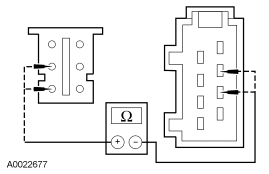
| K2 CHECK CIRCUITS 982 (YE/LG) AND 983 (RD/LG) FOR AN OPEN | |
|
Yes INSTALL a new seat control switch. TEST the system for normal operation. DISCONNECT the battery ground cable. DISCONNECT the restraint system diagnostic tool from the passenger seat safety belt buckle pretensioner electrical connector. CONNECT the passenger seat safety belt buckle pretensioner electrical connector. For vehicles equipped with seat side air bags, DISCONNECT the restraint system diagnostic tool from passenger seat side air bag module C316. CONNECT passenger seat side air bag module C316. For all vehicles, REPOWER the supplemental restraint system (SRS). REFER to Section 501-20B. No REPAIR the affected circuit(s). TEST the system for normal operation. DISCONNECT the battery ground cable. DISCONNECT the restraint system diagnostic tool from the passenger seat safety belt buckle pretensioner electrical connector. CONNECT the passenger seat safety belt buckle pretensioner electrical connector. For vehicles equipped with seat side air bags, DISCONNECT the restraint system diagnostic tool from passenger seat side air bag module C316. CONNECT passenger seat side air bag module C316. For all vehicles, REPOWER the supplemental restraint system (SRS). REFER to Section 501-20B. |
| K3 CHECK CIRCUIT 983 (RD/LG) FOR VOLTAGE TO THE SEAT TRACK MOTOR ASSEMBLY | |
|
Yes GO to K4. No INSTALL a new seat control switch. TEST the system for normal operation. DISCONNECT the battery ground cable. DISCONNECT the restraint system diagnostic tool from the passenger seat safety belt buckle pretensioner electrical connector. CONNECT the passenger seat safety belt buckle pretensioner electrical connector. For vehicles equipped with seat side air bags, DISCONNECT the restraint system diagnostic tool from passenger seat side air bag module C316. CONNECT passenger seat side air bag module C316. For all vehicles, REPOWER the supplemental restraint system (SRS). REFER to Section 501-20B. |
| K4 CHECK CIRCUIT 982 (YE/LG) FOR VOLTAGE TO THE SEAT TRACK MOTOR ASSEMBLY | |
|
Yes INSTALL a new seat track. REFER to Seat Track — Power in this section. TEST the system for normal operation. DISCONNECT the battery ground cable. DISCONNECT the restraint system diagnostic tool from the passenger seat safety belt buckle pretensioner electrical connector. CONNECT the passenger seat safety belt buckle pretensioner electrical connector. For vehicles equipped with seat side air bags, DISCONNECT the restraint system diagnostic tool from passenger seat side air bag module C316. CONNECT passenger seat side air bag module C316. For all vehicles, REPOWER the supplemental restraint system (SRS). REFER to Section 501-20B. No INSTALL a new seat control switch. TEST the system for normal operation. DISCONNECT the battery ground cable. DISCONNECT the restraint system diagnostic tool from the passenger seat safety belt buckle pretensioner electrical connector. CONNECT the passenger seat safety belt buckle pretensioner electrical connector. For vehicles equipped with seat side air bags, DISCONNECT the restraint system diagnostic tool from passenger seat side air bag module C316. CONNECT passenger seat side air bag module C316. For all vehicles, REPOWER the supplemental restraint system (SRS). REFER to Section 501-20B. |
Parts & tools for this job For 2007 Ford Taurus
- TOOLTrim removal tool kitSearch: trim removal tool kit
- PARTTouch-up paintSearch: Ford touch up paint
- PARTPanel clip assortmentSearch: Ford panel clips assortment
Links open Amazon search results in a new tab. As an Amazon Associate I earn from qualifying purchases.