
Tempo L4-122 2.0L DSL (1984)
Valve Clearance: Adjustments
Valve Arrangement
4-120.................................................................................................................................................................................................................E-I-E-I-E-I-E-I
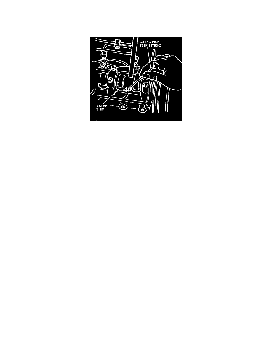
Fig. 5 Removing adjusting shim from cam follower
Valves, Adjust
1.
Disconnect breather hose from intake manifold and remove camshaft cover.
2.
Rotate crankshaft until No. 1 piston is at TDC.
3.
Using a suitable feeler gauge, check valve shim to cam lobe clearance for Nos. 1 and 2 intake valves and Nos. 1 and 3 exhaust valves. Intake valve
clearance should be .008---.011 in., exhaust valves clearance should be .011---.015 in.
4.
Rotate crankshaft one complete revolution. Measure valve clearance for Nos. 3 and 4 intake valves and Nos. 2 and 4 exhaust valves. If measured
clearance is not to specification, proceed as follows:
a. Rotate crankshaft until lobe of valve to be adjusted is facing downward.
b. Install cam follower retainer tool No. T84P-6513B or equivalent.
c. Rotate crankshaft until cam lobe is on base circle. Using tool No. T71P-19703C or equivalent, Fig. 5, pry valve adjusting shim out of the cam
follower. If the valve was tight, select a shim with a smaller thickness. If the valve was loose, select a shim with a larger thickness. Valve
shims are available in thicknesses ranging from .134---.181 in. (3.40---4.60 mm). Shim thickness is stamped on valve shim. Install
shim with numbers facing downward.
5.
Rotate crankshaft until cam lobe is facing downward and remove cam follower retainer.
6.
Recheck valve clearance. Repeat steps 2 through 4 for each valve to be adjusted.