
Tempo L4-122 2.0L DSL (1984)
Speedometer Gear, A/T: All Technical Service Bulletins
A/T Speedometer Gear - Installation Precaution
Article No. 84-17-12
TRANSMISSION - AUTOMATIC - ATX
-
SPEEDOMETER OR GOVERNOR DRIVE GEAR DAMAGE
FORD 1981-84 ESCORT, EXP, TEMPO
LINCOLN-MERCURY 1981-84 LYNX, LN7, TOPAZ
Driving the speedo gear and retainer assembly too far into the case can damage the drive (17285) gear and its mating components (i.e., speedo driven
gear [17281] and governor driven gear [7F419]), because it allow the retainer to contact the drive gear (17285) teeth. Misalignment of the retainer into
the case may also allow the retainer to extend too far into the case and contact the drive gear. Either of the above conditions can result in damage or
premature wearing of the speedometer and governor gears. The result is a loss of speedometer speed control or governor function. If either driven gear is
replaced, then the drive gear and the other driven gear should be inspected and replaced if necessary. Governor driven gears that exhibited an "hour
glass" wear pattern will require the entire governor gear assembly (7C053) to be replaced due to possible internal damage.
Additionally, some vehicles have a speedometer gear with a plastic stem where the speedometer cable is inserted that extends past the end of the retainer.
Tapping on the extended plastic end of the speedometer gear may cause distortion of the stem and inhibit speedometer cable installation.
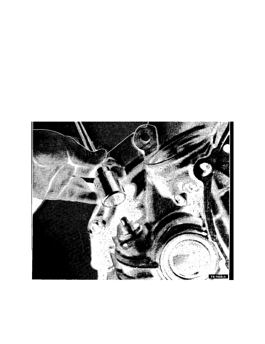
FIGURE 11
The recommended procedure for installation of the speedometer gear and retainer assembly is as follows:
1.
Lightly lubricate the O-ring seal on the speedo driven gear retainer with a thin film of grease.
2.
Align the relief in the retainer with the retaining pin hole in the case (Figure 11).
CAUTION: TAPPING DIRECTLY ON THE SPEEDOMETER GEAR ASSEMBLY MAY CAUSE DAMAGE TO THE PLASTIC DRIVEN GEAR.
3.
Place the socket required for installation and removal of the engine oil pressure sending unit (Proto tool #6524), or equivalent, on the gear and