| Diagnosis and Testing Refer to Wiring Diagrams Section 412-00, for schematic and connector information. Special Tool(s) | | Terminal Probe Kit 418-S035 | General Equipment Worldwide Diagnostic System (WDS) Service unit or manometer head Digital Multimeter (compatible with K-type thermocouple) Thermometer - Fluke 80 PK-8 (FSE number 260 4102 001 07) Inspection and Checking - Visually CHECK for any obvious mechanical or electrical damage.
Visual Inspection | Mechanical | Electrical | - Drive belt
- Refrigerant lines
- Condenser core
- Refrigerant compressor
| - Fuses
- Wiring harness
- Connectors
| - RECTIFY any obvious causes for a concern found during the visual inspection before performing any further tests. CHECK the operation of the system.
- If the concern persists after the visual inspection, CARRY OUT a fault diagnosis on the powertrain control module (PCM) and the instrument cluster with WDS and RECTIFY any displayed faults in accordance with the fault description. CHECK the operation of the system.
- If no fault is stored in the fault memory, PROCEED with the symptom chart according to the fault symptom.
- Following checking or elimination of the fault and after completion of operations, the fault memories of all vehicle modules must be READ OUT and any stored faults must be DELETED. READ OUT all fault memories again following a road test.
Refrigerant Circuit - Quick Check WARNING:The air conditioning system is filled with refrigerant R134a. Observe "Health and Safety Precautions". For further information
REFER to: Health and Safety Precautions (100-00 General Information, Description and Operation).
Refrigerant circuit check WARNING:Under certain circumstances, refrigerant lines and A/C components may be extremely hot or cold. Exercising care, touch the refrigerant lines or A/C components in order to check this. Failure to observe this instruction can lead to injury. When the A/C system is operating, the following conditions should apply: - The refrigerant line from the A/C compressor to the A/C condenser must be hot.
- The refrigerant line from the A/C condenser to the fixed orifice tube must be warm, but not so hot as the refrigerant line mentioned above.
- Determine the difference in temperature upstream and downstream of the A/C condenser by measuring the temperatures. Depending on the ambient temperature, the temperature difference should be more than 20°. If the temperature difference is less, check the condenser for contamination or damage to the fins as well as operation of the radiator fan.
- The refrigerant line between the fixed orifice tube and the evaporator must be cold from the point where the fixed orifice tube is installed. Depending on the weather, the refrigerant line may also have ice on its surface.
- The refrigerant line between the evaporator and the A/C compressor including the refrigerant accumulator must be cold.
Evaporator outlet temperature test To test the power of the A/C system, the temperature of the evaporator outlet line must be measured. To do this, the following preconditions must be met: - Open all windows.
- Set the air distribution to the defrost/dashboard position and open all the ventilation nozzles.
- DO NOT switch on recirculated air.
- Select lowest blower switch setting.
- Select lowest temperature setting.
NOTE:The temperature measurement cannot be done with a thermometer which makes no contact. The surface reflection from the metal line may cause incorrect readings. Connect the temperature sensor (Fluke 80 PK-8) to the outlet line of the evaporator. The temperature sensor must be positioned as closely as possible to the evaporator. Connect the temperature sensor to the multimeter. Start the engine and allow it to idle. Switch on the air-conditioning system. After three minutes, measure the surface temperature of the evaporator outlet line. If the temperature measured is 2° C or less, the A/C system is working correctly. If the temperature is higher, the A/C system may be under-filled. For further information, refer to REFER to: (412-00 Climate Control System - General Information) Specifications (Specifications), Air Conditioning (A/C) System Recovery, Evacuation and Charging (General Procedures). Frequent faults and their causes If the cooling power of the A/C system is not adequate, make certain that the temperature control flaps are operating correctly. - No or poor cooling performance:
- Blockage or restriction in one of the refrigerant lines or in the suction accumulator. By comparing temperatures at the refrigerant lines or at the suction accumulator, the location of the blockage or restriction can easily be identified. The blockage or restriction is located at the point where the temperature difference is identified. Note: A temperature difference in the area of the fixed orifice tube is normal. Once the location of the blockage or restriction has been detected, check the relevant component and renew if necessary. - Sudden poor cooling performance. After the air conditioning has been switched off for approx. 5 minutes, the cooling performance returns to normal:
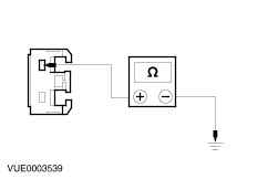
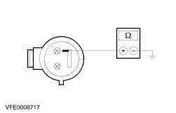
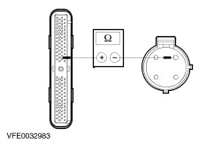
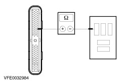
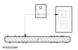
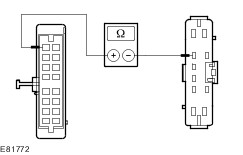
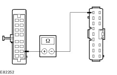
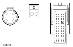
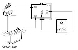
- Fixed orifice tube iced up. The cause for an iced-up fixed orifice tube is moisture in the refrigerant circuit. In order to ensure that moisture is completely removed from the refrigerant circuit, the suction accumulator must be renewed and the evacuation time must be extended to 2-3 hours. For further information, refer to REFER to: Suction Accumulator (412-03 Air Conditioning, Removal and Installation), Air Conditioning (A/C) System Recovery, Evacuation and Charging (412-00 Climate Control System - General Information, General Procedures). Symptom Chart Symptom Chart | Symptom | Possible Sources | Action | | Blower motor inoperative / partly inoperative | * Fuse(s) * Circuit(s) * Blower motor * Blower switch * Blower resistor assembly | * | | Blower motor running continuously | * Blower switch * Circuit(s) | * | | Air conditioning inoperative (blower function OK) | * Fuse(s) * Circuit(s) * Refrigerant quantity * Air conditioning clutch * Refrigerant compressor clutch diode * Refrigerant high-pressure switch * Refrigerant low-pressure switch * Air conditioning clutch relay * Powertrain control module (PCM) * Climate control system control assembly * instrument Cluster | * | | Malfunction of the recirculated air flap | * Circuit(s) * Actuator – recirculated air flap * Recirculated air flap * Climate control system control assembly * Dehumidification switch | * | | Refrigerant compressor inoperative when switch set to 'Defrost/demist windshield' (other functions of the control panel for the climate control system OK) | * Circuit(s) * Dehumidification switch * Climate control system control assembly | * | System Checks | PINPOINT TEST A : BLOWER MOTOR INOPERATIVE / PARTLY INOPERATIVE | | TEST CONDITIONS | DETAILS/RESULTS/ACTIONS | | A1: CHECK ALL SPEED SETTINGS OF THE BLOWER MOTOR | | | 1 Ignition switch in position II. | | | 2 Switch the blower switch through all speed settings. | | | Is the blower motor inoperative in all the switch positions? Yes No - The blower motor is only inoperative in switch position 4: GO to A8. - The blower motor is inoperative in switch positions 1, 2 and/or 3: GO to A9. | | A2: CHECK FUSE F64 | | | 1 Ignition switch in position 0. | | | 2 CHECK fuse F64 (BJB). | | | Is the fuse OK? Yes No RENEW fuse F64 (30 A). CHECK the operation of the system. If the fuse blows again, LOCATE and REPAIR the short using the Wiring Diagrams. | | A3: CHECK THE VOLTAGE AT FUSE F64 | | | 1 Connect fuse F64 (BJB). | | | 2 Ignition switch in position II. | | | 3 Measure voltage between fuse F64 (30 A) and ground. | | | Does the meter display battery voltage? Yes No REPAIR the voltage supply to fuse F64 using the Wiring Diagrams. CHECK the operation of the system. | | A4: CHECK THE VOLTAGE AT HEATER BLOWER MOTOR | | | 1 Ignition switch in position 0. | | | 2 Disconnect connector C789 from blower motor. | | | 3 Ignition switch in position II. | | | 4 Measure the voltage between the blower motor, connector C789, pin 1, circuit 15-FA18 (GN/OG), wiring harness side and ground. | | | Does the meter display battery voltage? Yes No LOCATE and REPAIR break in circuit 15-FA18 (GN/OG), between blower motor and fuse F64 using the Wiring Diagrams. CHECK the operation of the system. | | A5: CHECK THE GROUND CONNECTION OF THE BLOWER MOTOR | | | 1 Ignition switch in position 0. | | | 2 Set the blower switch to position 4. | | | 3 Measure the resistance between the blower motor, connector C789, pin 2, circuit 31S-FA18 (BK/RD), wiring harness side and ground. | | | Is a resistance of less than 2 Ohm registered? Yes RENEW the blower motor. CHECK the operation of the system. No | | A6: CHECK THE CIRCUIT BETWEEN THE BLOWER MOTOR AND THE BLOWER SWITCH | | | 1 Disconnect connector C469 of heater blower switch. | | | 2 Measure the resistance between the blower motor, connector C789, pin 2, circuit 31S-FA18 (BK/RD), wiring harness side and the blower switch, connector C469, pin 6, circuit 31S-FA33 (BK/OG), wiring harness side. | | | Is a resistance of less than 2 Ohm registered? Yes No LOCATE and RECTIFY the open circuit in circuit 31S-FA18 (BK/RD) between the blower motor and soldered connection S24 with the aid of the Wiring Diagrams. CHECK the operation of the system. | | A7: CHECK THE GROUND CONNECTION OF THE BLOWER SWITCH | | | 1 Measure the resistance between the blower switch, connector C469, pin 2, circuit 31-FA25 (BK), wiring harness side and ground. | | | Is a resistance of less than 2 Ohm registered? Yes INSTALL A NEW blower switch. CHECK the operation of the system. No LOCATE and RECTIFY the break in circuit 31-FA25 (BK) between the blower switch and ground connection G14 using the Wiring Diagrams. CHECK the operation of the system. | | A8: CHECK THE CIRCUIT BETWEEN THE BLOWER MOTOR AND THE BLOWER SWITCH | | | 1 Ignition switch in position 0. | | | 2 Disconnect connector C469 of heater blower switch. | | | 3 Disconnect connector C789 from blower motor. | | | 4 Measure the resistance between the blower motor, connector C789, pin 2, circuit 31S-FA18 (BK/RD), wiring harness side and the blower switch, connector C469, pin 6, circuit 31S-FA33 (BK/OG), wiring harness side. | | | Is a resistance of less than 2 Ohm registered? Yes INSTALL A NEW blower switch. CHECK the operation of the system. No LOCATE and REPAIR the break in circuit 31S-FA33 (BK/OG) between the blower switch and soldered connection S24 using the Wiring Diagrams. CHECK the operation of the system. | | A9: CHECK THE HEATER BLOWER SWITCH | | | 1 Ignition switch in position 0. | | | 2 Disconnect connector C469 of heater blower switch. | | | 3 Ignition switch in position II. | | | 4 Measure the voltage between the blower switch, connector C469, pin 5, circuit 31S-FA32 (BK/BU), wiring harness side and ground. | | | 5 Measure the voltage between the blower switch, connector C469, pin 3, circuit 31S-FA31 (BK/YE), wiring harness side and ground. | | | 6 Measure the voltage between the blower switch, connector C469, pin 1, circuit 31S-FA30 (BK/WH), wiring harness side and ground. | | | Is battery voltage measured in all cases? Yes INSTALL A NEW blower switch. CHECK the operation of the system. No | | A10: CHECK THE CIRCUIT BETWEEN THE BLOWER MOTOR AND THE BLOWER RESISTOR | | | 1 Ignition switch in position 0. | | | 2 Disconnect connector C470 from blower resistor assembly. | | | 3 Ignition switch in position II. | | | 4 Measure the voltage between the blower resistor, connector C470, pin 1, circuit 31S-FA1 (BK/BU), wiring harness side and ground. | | | Does the meter display battery voltage? Yes No LOCATE and REPAIR the break in circuit 31S-FA1 (BK/BU) between soldered connection S24 and the blower resistor assembly using the Wiring Diagrams. CHECK the operation of the system. | | A11: CHECK THE CIRCUIT BETWEEN THE BLOWER RESISTOR AND THE BLOWER SWITCH | | | 1 Ignition switch in position 0. | | | 2 Measure the resistance between the blower resistor assembly, connector C470, pin 4, circuit 31S-FA32 (BK/BU), wiring harness side and the blower switch, connector C469, pin 5, circuit 31S-FA32 (BK/BU), wiring harness side. | | | Is a resistance of less than 2 Ohm registered? Yes No LOCATE and REPAIR the break in circuit 31S-FA32 (BK/BU) between the blower resistor assembly and the blower switch using the Wiring Diagrams. CHECK the operation of the system. | | A12: CHECK THE CIRCUIT BETWEEN THE BLOWER RESISTOR AND THE BLOWER SWITCH | | | 1 Measure the resistance between the blower resistor assembly, connector C470, pin 2, circuit 31S-FA31 (BK/YE), wiring harness side and the blower switch, connector C469, pin 3, circuit 31S-FA31 (BK/YE), wiring harness side. | | | Is a resistance of less than 2 Ohm registered? Yes No LOCATE and REPAIR the break in circuit 31S-FA31 (BK/YE) between the blower resistor assembly and the blower switch using the Wiring Diagrams. CHECK the operation of the system. | | A13: CHECK THE CIRCUIT BETWEEN THE BLOWER RESISTOR AND THE BLOWER SWITCH | | | 1 Measure the resistance between the blower resistor assembly, connector C470, pin 3, circuit 31S-FA30 (BK/WH), wiring harness side and the blower switch, connector C469, pin 1, circuit 31S-FA30 (BK/WH), wiring harness side. | | | Is a resistance of less than 2 Ohm registered? Yes RENEW the blower resistor assembly. CHECK the operation of the system. No LOCATE and REPAIR the break in circuit 31S-FA30 (BK/WH) between the blower resistor assembly and the blower switch using the Wiring Diagrams. CHECK the operation of the system. | | PINPOINT TEST B : BLOWER MOTOR RUNNING CONTINUOUSLY | | TEST CONDITIONS | DETAILS/RESULTS/ACTIONS | | B1: CHECK THE HEATER BLOWER SWITCH | | | 1 Ignition switch in position 0. | | | 2 Disconnect connector C469 of heater blower switch. | | | 3 Ignition switch in position II. | | | 4 Check function of blower motor. | | | Does the blower motor run continuously? Yes No INSTALL A NEW blower switch. CHECK the operation of the system. | | B2: CHECK THE CIRCUITS AT THE BLOWER RESISTOR | | | 1 Ignition switch in position 0. | | | 2 Disconnect connector C470 from blower resistor assembly. | | | 3 Ignition switch in position II. | | | 4 Check function of blower motor. | | | Does the blower motor run continuously? Yes CHECK all circuits connected to soldered connection S24 for short to ground using the Wiring Diagrams and REPAIR any short circuit(s) found. CHECK the operation of the system. No CHECK all circuits between the blower resistor and the blower switch for a short to ground using the Wiring Diagrams and RECTIFY any short circuit(s) found. CHECK the operation of the system. | | PINPOINT TEST C : AIR CONDITIONING INOPERATIVE (BLOWER FUNCTION OK) | | TEST CONDITIONS | DETAILS/RESULTS/ACTIONS | | C1: CHECK THE REFRIGERANT PRESSURE IN THE REFRIGERANT CIRCUIT | | | 1 Ignition switch in position 0. | | | CAUTION:The refrigerant identification equipment must be used before checking, otherwise the service unit may become contaminated. Contaminated refrigerant must be disposed of as hazardous waste. Always follow the manufacturer's instructions when using the service units. CAUTION:When recovering the refrigerant do not allow it to enter the atmosphere under any circumstances. 2 Connect the R-134a refrigerant center or the set of R134a pressure gauges to the refrigerant circuit and measure the refrigerant pressure in the refrigerant circuit. | | | Is a refrigerant pressure of more than 3.2 bar measured? Yes No PERFORM a leak test on the refrigerant circuit REFER to: Fluorescent Dye Leak Detection (412-00 Climate Control System - General Information, General Procedures). CHARGE the system with the correct amount of refrigerant REFER to: (412-00 Climate Control System - General Information) Specifications (Specifications), Air Conditioning (A/C) System Recovery, Evacuation and Charging (General Procedures). CHECK the operation of the system. | | C2: CHECK FUSE F59 | | | 1 CHECK fuse F59 (CJB). | | | Is the fuse OK? Yes No RENEW fuse F59 (7.5 A). CHECK the operation of the system. If the fuse blows again, LOCATE and REPAIR the short using the Wiring Diagrams. | | C3: CHECK THE VOLTAGE AT FUSE F59 | | | 1 Connect fuse F59 (CJB). | | | 2 Measure the voltage between fuse F59 (7.5 A) and ground. | | | Does the meter display battery voltage? Yes No REPAIR the voltage supply to fuse F59 using the Wiring Diagrams. CHECK the operation of the system. | | C4: CHECK FUSE F34 | | | 1 CHECK fuse F34 (CJB). | | | Is the fuse OK? Yes No RENEW fuse F34 (7.5 A). CHECK the operation of the system. If the fuse blows again, LOCATE and REPAIR the short using the Wiring Diagrams. | | C5: CHECK THE VOLTAGE AT FUSE F34 | | | 1 Connect fuse F34 (CJB). | | | 2 Ignition switch in position II. | | | 3 Measure the voltage between fuse F34 (7.5 A) and ground. | | | Does the meter display battery voltage? Yes No REPAIR the voltage supply to fuse F34 using the Wiring Diagrams. CHECK the operation of the system. | | C6: CHECK FUSE F48 | | | 1 Ignition switch in position 0. | | | 2 CHECK Fuse F48 (CJB). | | | Is the fuse OK? Yes No INSTALL a new fuse F48 (7.5 A). CHECK the operation of the system. If the fuse blows again, LOCATE and REPAIR the short using the Wiring Diagrams. | | C7: CHECK THE VOLTAGE AT FUSE F48 | | | 1 Connect Fuse F48 (CJB). | | | 2 Measure the voltage between fuse F48 (7.5 A) and ground. | | | Does the meter display battery voltage? Yes No REPAIR the voltage supply to fuse F48 using the Wiring Diagrams. CHECK the operation of the system. | | C8: CHECK FUSE F60 | | | 1 CHECK Fuse F60 (CJB). | | | Is the fuse OK? Yes No RENEW fuse F60 (7.5 A). CHECK the operation of the system. If the fuse blows again, LOCATE and REPAIR the short using the Wiring Diagrams. | | C9: CHECK THE VOLTAGE AT FUSE F60 | | | 1 Connect Fuse F60 (CJB). | | | 2 Ignition switch in position II. | | | 3 Measure the voltage between fuse F60 (7.5 A) and ground. | | | Does the meter display battery voltage? Yes No REPAIR the voltage supply to fuse F60 with the aid of the Wiring Diagrams. CHECK the operation of the system. | | C10: CHECK FUSE F26 | | | 1 Ignition switch in position 0. | | | 2 CHECK fuse F26 (BJB). | | | Is the fuse OK? Yes No RENEW fuse F26 (10 A). CHECK the operation of the system. If the fuse blows again after switching the air conditioning on, CHECK the refrigerant compressor clutch diode and RENEW as necessary. If the refrigerant compressor clutch diode is OK, LOCATE and RECTIFY the short circuit with the aid of the Wiring Diagrams. | | C11: CHECK THE VOLTAGE AT FUSE F26 | | | 1 Connect fuse F26 (BJB). | | | 2 Measure the voltage between fuse F26 (10 A) and ground. | | | Does the meter display battery voltage? Yes No REPAIR the voltage supply to fuse F26 using the Wiring Diagrams. CHECK the operation of the system. | | C12: CHECK THE VOLTAGE AT THE A/C CLUTCH RELAY | | | 1 Disconnect A/C clutch relay from socket C1011 (BJB). | | | 2 Measure the voltage between the A/C clutch relay, socket C1011, pin 3, circuit 30-FA12 (RD), wiring harness side and ground. | | | Does the meter display battery voltage? Yes No LOCATE and RECTIFY the break in circuit 30-FA12 (RD) between the A/C clutch relay and fuse F26 using the Wiring Diagrams. CHECK the operation of the system. | | C13: CHECK THE CONTROL VOLTAGE AT THE AIR CONDITIONING CLUTCH RELAY | | | 1 Ignition switch in position II. | | | 2 Measure the voltage between the air conditioning clutch relay, socket C1011, pin 1, circuit 15-FA11 (GN/YE), wiring harness side and ground. | | | Does the meter display battery voltage? Yes No LOCATE and RECTIFY the break in circuit 15-FA11 (GN/YE) between the A/C clutch relay and soldered connection S117 (vehicles built from 07/2006: soldered connection S54) with the aid of the Wiring Diagrams. CHECK the operation of the system. | | C14: CHECK THE A/C CLUTCH ELECTRICAL CIRCUIT | | | 1 Ignition switch in position 0. | | | 2 Use a fused test cable (10 A) to bridge the air conditioning clutch relay, socket C1011, pin 3 and pin 5, wiring harness side. | | | 3 Check that the A/C system clutch operates correctly. | | | Does the air conditioning clutch work? Yes No | | C15: CHECK THE ELECTRICAL CIRCUIT BETWEEN THE A/C CLUTCH RELAY AND THE A/C CLUTCH FOR OPEN CIRCUIT | | | 1 Disconnect Connector C952 from the A/C clutch. | | | 2 Use a fused test cable (10 A) to bridge the air conditioning clutch relay, socket C1011, pin 3 and pin 5, wiring harness side. | | | 3 Measure the voltage between A/C clutch, connector C952, pin 1, circuit 15S-FA6 (GN/YE), wiring harness side and ground. | | | Does the meter display battery voltage? Yes No LOCATE and REPAIR the open circuit between the air conditioning clutch relay and air conditioning clutch using the Wiring Diagrams. CHECK the operation of the system. | | C16: CHECK THE GROUND CONNECTION OF THE A/C CLUTCH | | | 1 Measure the resistance between the air conditioning clutch, connector C952, pin 2, circuit 31-FA6 (BK), wiring harness side and ground. | | | Is a resistance of less than 2 Ohm registered? Yes INSTALL A NEW air conditioning clutch. CHECK the operation of the system. No LOCATE and REPAIR the break in circuit 31-FA6 (BK) between the A/C clutch and soldered connection S109 using the Wiring Diagrams. CHECK the operation of the system. | | C17: CHECK THE VOLTAGE AT THE REFRIGERANT LOW PRESSURE SWITCH | | | 1 Disconnect connector C692 from refrigerant low-pressure switch. | | | 2 Ignition switch in position II. | | | 3 Switch on the blower. | | | 4 Switch on the air-conditioning system. | | | 5 Measure the voltage between the refrigerant low-pressure switch, connectorr C692, pin 4, circuit 15S-FA17 (GN/OG) (vehicles built from 07/2006: circuit 91S-FA17 (BK/RD)), wiring harness side and ground. | | | Does the meter display battery voltage? Yes No | | C18: CHECK REFRIGERANT LOW-PRESSURE SWITCH | | | 1 Ignition switch in position 0. | | | 2 Measure the resistance at the A/C low pressure switch, connector C692, between pin 1 and pin 4, component side. | | | Is a resistance of less than 2 Ohm registered? Yes - vehicles with 1.8L (55 KW) diesel engine and vehicles with LPG fuel system: GO to C19. - vehicles with 1.8L (66 KW) diesel engine: GO to C21. - vehicles with 85 KW engine, except vehicles with LPG fuel system: GO to C23. No RENEW the refrigerant low-pressure switch. CHECK the operation of the system. | | C19: CHECK ELECTRICAL CIRCUIT BETWEEN A/C LOW PRESSURE SWITCH AND POWERTRAIN CONTROL MODULE (PCM) FOR OPEN CIRCUIT - VEHICLES WITH 1.8L (55 KW) DIESEL ENGINE AND VEHICLES WITH LPG FUEL SYSTEM: | | | 1 Disconnect connector C415 from PCM. | | | 2 Measure the resistance between PCM, connector C415, pin 41, circuit 15S-RE8 (GN/YE), wiring harness side and A/C low pressure switch, connector C692, pin 1, circuit 15S-RE8 (GN/YE), wiring harness side. | | | Is a resistance of less than 2 Ohm registered? Yes No LOCATE and REPAIR the break in circuit 15S-RE8 (GN/YE) between the A/C low pressure switch and the PCM using the Wiring Diagrams. CHECK the operation of the system. | | C20: CHECK ELECTRICAL CIRCUIT BETWEEN A/C CLUTCH RELAY AND PCM FOR OPEN CIRCUIT - VEHICLES WITH 1.8L (55 KW) DIESEL ENGINE AND VEHICLES WITH LPG FUEL SYSTEM | | | 1 Measure the resistance between the PCM, connector C415, pin 69, circuit 31S-FA11 (BK/YE), wiring harness side and the A/C clutch relay, socket C1011, pin 2, circuit 31S-FA11 (BK/YE), wiring harness side. | | | Is a resistance of less than 2 Ohm registered? Yes No LOCATE and RECTIFY the break in circuit 31S-FA11 (BK/YE) between PCM and the air conditioning clutch relay using the Wiring Diagrams. CHECK the operation of the system. | | C21: CHECK ELECTRICAL CIRCUIT BETWEEN A/C LOW PRESSURE SWITCH AND POWERTRAIN CONTROL MODULE (PCM) FOR OPEN CIRCUIT - VEHICLES WITH 1.8L (66 KW) DIESEL ENGINE | | | 1 Disconnect connector C414 of PCM. | | | 2 Measure the resistance between PCM, connector C414, pin 19, circuit 15S-RE8 (GN/YE), wiring harness side and A/C low pressure switch, connector C692, pin 1, circuit 15S-RE8 (GN/YE), wiring harness side. | | | Is a resistance of less than 2 Ohm registered? Yes No LOCATE and REPAIR the break in circuit 15S-RE8 (GN/YE) between the A/C low pressure switch and the PCM using the Wiring Diagrams. CHECK the operation of the system. | | C22: CHECK ELECTRICAL CIRCUIT BETWEEN A/C CLUTCH RELAY AND PCM FOR OPEN CIRCUIT - VEHICLES WITH 1.8L (66 KW) DIESEL ENGINE | | | 1 Measure the resistance between the PCM, connector C414, pin 79, circuit 31S-FA11 (BK/YE), wiring harness side and the A/C clutch relay, socket C1011, pin 2, circuit 31S-FA11 (BK/YE), wiring harness side. | | | Is a resistance of less than 2 Ohm registered? Yes No LOCATE and RECTIFY the break in circuit 31S-FA11 (BK/YE) between PCM and the air conditioning clutch relay using the Wiring Diagrams. CHECK the operation of the system. | | C23: CHECK ELECTRICAL CIRCUIT BETWEEN A/C LOW PRESSURE SWITCH AND POWERTRAIN CONTROL MODULE (PCM) FOR OPEN CIRCUIT - VEHICLES WITH 85 KW ENGINE EXCEPT VEHICLES WITH LPG FUEL SYSTEM: | | | 1 Disconnect connector C416 of PCM. | | | 2 Measure the resistance between PCM, connector C416, pin 10, circuit 15S-RE8 (GN/YE), wiring harness side and A/C low pressure switch, connector C692, pin 1, circuit 15S-RE8 (GN/YE), wiring harness side. | | | Is a resistance of less than 2 Ohm registered? Yes No LOCATE and REPAIR the break in circuit 15S-RE8 (GN/YE) between the A/C low pressure switch and the PCM using the Wiring Diagrams. CHECK the operation of the system. | | C24: CHECK ELECTRICAL CIRCUIT BETWEEN A/C CLUTCH RELAY AND PCM FOR OPEN CIRCUIT - VEHICLES WITH 85 KW ENGINE EXCEPT VEHICLES WITH LPG FUEL SYSTEM: | | | 1 Measure the resistance between the PCM, connector C416, pin 54, circuit 31S-FA11 (BK/YE), wiring harness side and the A/C clutch relay, socket C1011, pin 2, circuit 31S-FA11 (BK/YE), wiring harness side. | | | Is a resistance of less than 2 Ohm registered? Yes No LOCATE and RECTIFY the break in circuit 31S-FA11 (BK/YE) between PCM and the air conditioning clutch relay using the Wiring Diagrams. CHECK the operation of the system. | | C25: CHECK AIR CONDITIONING CLUTCH RELAY | | | 1 Check the A/C clutch relay according to the component check at the end of the section. | | | Is the air conditioning clutch relay OK? Yes TEST the PCM and RENEW as necessary. CHECK the operation of the system. No RENEW the air conditioning clutch relay. CHECK and if necessary RENEW the refrigerant compressor clutch diode. CHECK the operation of the system. | | C26: CHECK VOLTAGE AT REFRIGERANT HIGH-PRESSURE SWITCH | | | 1 Ignition switch in position 0. | | | 2 Disconnect connector C882 from refrigerant high-pressure switch. | | | 3 Ignition switch in position II. | | | 4 Switch on the blower. | | | 5 Switch on the air-conditioning system. | | | 6 Measure the voltage between the A/C high pressure switch, connector C882, pin 1, circuit 15S-FA38 (GN/RD), wiring harness side and ground. | | | Does the meter display battery voltage? Yes No Vehicles built from 07/2006:LOCATE and REPAIR the break in circuit 91-FA38 (BK/OG) between the refrigerant high-pressure switch and soldered connection S118 using the Wiring Diagrams. CHECK the operation of the system. | | C27: CHECK REFRIGERANT HIGH-PRESSURE SWITCH | | | 1 Ignition switch in position 0. | | | 2 Measure the resistance at the A/C high pressure switch, connector C882, between pin 1 and pin 4, component side. | | | Is a resistance of less than 2 Ohm registered? Yes LOCATE and RECTIFY the break in circuit 15S-FA17 (GN/OG) (vehicles built from 07/2006: circuit 91S-FA17 BK/RD)) between the refrigerant low-pressure switch and the refrigerant high-pressure switch with the aid of the Wiring Diagrams. CHECK the operation of the system. No RENEW the refrigerant high-pressure switch. CHECK the operation of the system. | | C28: CHECK THE VOLTAGE AT THE CONTROL PANEL OF THE CLIMATE CONTROL SYSTEM - PIN 8 | | | 1 Ignition switch in position 0. | | | 2 Disconnect Connector C380 from the control panel for the climate control system. | | | 3 Measure the voltage between the control panel for the climate control system, connector C380, pin 8, circuit 29-FA13 (OG), wiring harness side and ground. | | | Does the meter display battery voltage? Yes No | | C29: CHECK THE CIRCUIT BETWEEN THE CONTROL PANEL FOR THE CLIMATE CONTROL SYSTEM AND THE CJB FOR OPEN CIRCUIT - VEHICLES BUILT UP TO 07/2006 | | | 1 Disconnect Connector C16 from CJB. | | | 2 Measure the resistance between the control panel for the climate control system, connector C380, pin 8, circuit 29-FA13 (OG), wiring harness side and the CJB, connector C16, pin 9, circuit 29-FA13 (OG), wiring harness side. | | | Is a resistance of less than 2 Ohm registered? Yes CHECK the CJB and RENEW as necessary. CHECK the operation of the system. No LOCATE and RECTIFY the break in circuit 29-FA13 (OG) between the control panel for the climate control system and the CJB using the Wiring Diagrams. CHECK the operation of the system. | | C30: CHECK THE CIRCUIT BETWEEN THE CONTROL PANEL FOR THE CLIMATE CONTROL SYSTEM AND THE CJB FOR OPEN CIRCUIT - VEHICLES BUILT FROM 07/2006 | | | 1 Disconnect Connector C11 from CJB. | | | 2 Measure the resistance between the control panel for the climate control system, connector C380, pin 8, circuit 29-FA13 (OG), wiring harness side and the CJB, connector C11, pin 8, circuit 29-FA13 (OG), wiring harness side. | | | Is a resistance of less than 2 Ohm registered? Yes CHECK the CJB and RENEW as necessary. CHECK the operation of the system. No LOCATE and RECTIFY the break in circuit 29-FA13 (OG) between the control panel for the climate control system and the CJB using the Wiring Diagrams. CHECK the operation of the system. | | C31: CHECK THE VOLTAGE AT THE CONTROL PANEL OF THE CLIMATE CONTROL SYSTEM - PIN 10 | | | 1 Ignition switch in position II. | | | 2 Measure the voltage between the control panel for the climate control system, connector C380, pin 10, circuit 15-FA13 (GN/RD), wiring harness side and ground. | | | Does the meter display battery voltage? Yes No | | C32: CHECK THE CIRCUIT BETWEEN THE CONTROL PANEL FOR THE CLIMATE CONTROL SYSTEM AND THE CJB FOR OPEN CIRCUIT - VEHICLES BUILT UP TO 07/2006 | | | 1 Disconnect connector C10 from CJB. | | | 2 Measure the resistance between the control panel for the climate control system, connector C380, pin 10, circuit 15-FA13 (GN/RD), wiring harness side and the CJB, connector C10, pin 8, circuit 15-FA13 (GN/RD), wiring harness side. | | | Is a resistance of less than 2 Ohm registered? Yes CHECK the CJB and RENEW as necessary. CHECK the operation of the system. No LOCATE and RECTIFY the break in circuit 15-FA13 (GN/RD) between the control panel for the climate control system and the CJB with the aid of the Wiring Diagrams. CHECK the operation of the system. | | C33: CHECK THE CIRCUIT BETWEEN THE CONTROL PANEL FOR THE CLIMATE CONTROL SYSTEM AND THE CJB FOR OPEN CIRCUIT - VEHICLES BUILT FROM 07/2006 | | | 1 Disconnect Connector C11 from CJB. | | | 2 Measure the resistance between the control panel for the climate control system, connector C380, pin 10, circuit 15-FA13 (GN/RD), wiring harness side and the CJB, connector C11, pin 15, circuit 15-FA13 (GN/RD), wiring harness side. | | | Is a resistance of less than 2 Ohm registered? Yes CHECK the CJB and RENEW as necessary. CHECK the operation of the system. No LOCATE and RECTIFY the break in circuit 15-FA13 (GN/RD) between the control panel for the climate control system and the CJB with the aid of the Wiring Diagrams. CHECK the operation of the system. | | C34: CHECK THE GROUND CONNECTION OF THE CONTROL PANEL FOR THE CLIMATE CONTROL SYSTEM | | | 1 Ignition switch in position 0. | | | 2 Measure the resistance between the control panel for the climate control system, connector C380, pin 12, circuit 91-FA13 (BK/OG), wiring harness side and ground. | | | Is a resistance of less than 2 Ohm registered? Yes No LOCATE and RECTIFY the open circuit in circuit 91-FA13 (BK/OG) between the control panel for the climate control system and soldered connection S12 with the aid of the Wiring Diagrams. CHECK the operation of the system. | | C35: CHECK GROUND CONNECTION THROUGH BLOWER SWITCH | | | 1 Set the blower switch to position 1. | | | 2 Measure the resistance between the control panel for the climate control system, connector C380, pin 6, circuit 31S-FA26 (BK/RD), wiring harness side and ground. | | | Is a resistance of less than 2 Ohm registered? Yes Vehicles built from 07/2006:CHECK and if necessary RENEW the control panel for the climate control system. CHECK the operation of the system. No LOCATE and RECTIFY the break in circuit 31S-FA26 (BK/RD) between the control panel for the climate control system and the blower switch with the aid of the Wiring Diagrams. CHECK the operation of the system. | | C36: CHECK THE CIRCUIT BETWEEN THE CONTROL PANEL FOR THE CLIMATE CONTROL SYSTEM AND THE REFRIGERANT HIGH-PRESSURE SWITCH FOR OPEN CIRCUIT | | | 1 Measure the resistance between the control panel for the climate control system, connector C380, pin 9, circuit 15S-FA38 (GN/RD), wiring harness side and the refrigerant high pressure switch, connector C882, pin 1, circuit 15S-FA38 (GN/RD), wiring harness side. | | | Is a resistance of less than 2 Ohm registered? Yes CHECK and if necessary RENEW the control panel for the climate control system. CHECK the operation of the system. No LOCATE and REPAIR the break in circuit 15S-FA38 (GN/RD) between the control panel for the climate control system and the refrigerant high pressure switch with the aid of the Wiring Diagrams. CHECK the operation of the system. | | C37: CHECK THE A/C REQUEST SIGNAL IN THE POWERTRAIN CONTROL MODULE (PCM) | | | 1 Connect the diagnostic tool. | | | 2 Switch on the blower. | | | 3 Switch on the air-conditioning system. | | | 4 Using the diagnostic unit, select the PCM and check in the data logger whether an A/C request signal is displayed. | | | Is an A/C request signal displayed in the data logger of the PCM? Yes No | | C38: CHECK THE CIRCUIT BETWEEN THE PCM AND THE REFRIGERANT LOW PRESSURE SWITCH FOR OPEN CIRCUIT | | | 1 Ignition switch in position 0. | | | 2 Disconnect connector C419 from the PCM. | | | 3 Measure the resistance between the refrigerant low-pressure switch, connector C692, pin 1, circuit 91S-RE8 (BK/YE), wiring harness side and the PCM, connector C419, pin E4, circuit 91S-RE8 (BK/YE), wiring harness side. | | | Is a resistance of less than 2 Ohm registered? Yes No LOCATE and REPAIR the break in circuit 91S-RE8 (BK/YE) between the refrigerant low-pressure switch and the PCM using the Wiring Diagrams. CHECK the operation of the system. | | C39: CHECK FOR OPEN CIRCUIT BETWEEN AIR CONDITIONING CLUTCH RELAY AND PCM | | | 1 Measure the resistance between the PCM, connector C418, pin F2, circuit 31S-FA11 (BK/YE), wiring harness side and the A/C clutch relay, socket C1011, pin 2, circuit 31S-FA11 (BK/YE), wiring harness side. | | | Is a resistance of less than 2 Ohm registered? Yes No LOCATE and REPAIR the break in circuit 31S-FA11 (BK/YE) between the refrigerant low-pressure switch and the PCM using the Wiring Diagrams. CHECK the operation of the system. | | C40: CHECK THE A/C REQUEST SIGNAL IN THE CENTRAL TIMER MODULE (CTM) | NOTE:The central timer module (CTM) is integrated in the instrument cluster. | | | 1 Switch on the blower. | | | 2 Switch on the air-conditioning system. | | | 3 Using the diagnostic unit, select the CTM and check in the data logger whether an A/C request signal is displayed. | | | Is an A/C request signal displayed in the data logger of the CTM? Yes CHECK and if necessary RENEW the instrument cluster. CHECK the operation of the system. No | | C41: CHECK THE CONTROL VOLTAGE AT THE INSTRUMENT CLUSTER | | | 1 Ignition switch in position 0. | | | 2 Disconnect Connector C809 from instrument cluster. | | | 3 Ignition switch in position II. | | | 4 Switch on the blower. | | | 5 Switch on the air-conditioning system. | | | 6 Measure the voltage at the instrument cluster, connector C809, between pin 23, circuit 15S-FA38 (GN/RD), wiring harness side and ground. | | | Does the meter display battery voltage? Yes CHECK and if necessary RENEW the instrument cluster. CHECK the operation of the system. No | | C42: CHECK FOR OPEN CIRCUIT BETWEEN THE CONTROL PANEL FOR THE CLIMATE CONTROL SYSTEM AND THE INSTRUMENT CLUSTER | | | 1 Ignition switch in position 0. | | | 2 Disconnect Connector C380 from the control panel for the climate control system. | | | 3 Measure the resistance between the control panel for the climate control system, connector C380, pin 9, circuit 15S-FA38 (GN/RD), wiring harness side and the instrument cluster, connector C809, pin 23, circuit 15S-FA38 (GN/RD), wiring harness side. | | | Is a resistance of less than 2 Ohm registered? Yes No LOCATE and REPAIR the break in circuit 15S-FA38 (GN/RD) between the control panel for the climate control system and the instrument cluster with the aid of the Wiring Diagrams. CHECK the operation of the system. | | PINPOINT TEST D : MALFUNCTION OF THE RECIRCULATED AIR FLAP | NOTE:The recirculated air flap is actuated by means of a DC motor. This is activated for a maximum of 7 seconds by the control panel for the climate control system following actuation of the recirculated air button. Opening and closing of the recirculated air flap is performed by reversing the polarity of the applied voltage. | NOTE:"Recirculated air" mode is not available when the "Defrost/demist windscreen" function is active. | | TEST CONDITIONS | DETAILS/RESULTS/ACTIONS | | D1: CHECK THE VOLTAGE AT THE AIR RECIRCULATION FLAP ACTUATOR | | | 1 Ignition switch in position 0. | | | 2 Disconnect connector C375 from air recirculation flap actuator. | | | 3 Ignition switch in position II. | | | 4 Set the air distribution to footwell. | | | 5 Measure the voltage at the air recirculation flap actuator, connector C375, between pin 2 and pin 4, wiring harness side. | | | 6 Actuate the recirculated air switch several times during the measurement. | | | Is a voltage of at least 10 V measured with alternating polarity? Yes CHECK the recirculated air flap for ease of movement and correct operation. If the air recirculation flap is OK, RENEW the air recirculation flap actuator. CHECK the operation of the system. No LHD vehicles built from 08/2004: GO to D4. RHD vehicles built from 08/2004: GO to D6. | | D2: CHECK THE CIRCUIT BETWEEN THE AIR RECIRCULATION FLAP ACTUATOR AND THE CONTROL PANEL FOR THE CLIMATE CONTROL SYSTEM FOR OPEN CIRCUIT - VEHICLES BUILT UP TO 08/2004 | | | 1 Ignition switch in position 0. | | | 2 Disconnect Connector C380 from the control panel for the climate control system. | | | 3 Measure the resistance between the air recirculation flap actuator, connector C375, pin 2 (RHD vehicles: pin 4), circuit 32-FA76 (WH/BU), wiring harness side and the control panel for the climate control system, connector C380, pin 14, circuit 32-FA76 (WH/BU), wiring harness side. | | | Is a resistance of less than 2 Ohm registered? Yes No LOCATE and REPAIR the break in circuit 32-FA76 (WH/BU) between the air recirculation flap actuator and the control panel for the climate control system with the aid of the Wiring Diagrams. CHECK the operation of the system. | | D3: CHECK THE CIRCUIT BETWEEN THE AIR RECIRCULATION FLAP ACTUATOR AND THE CONTROL PANEL FOR THE CLIMATE CONTROL SYSTEM FOR OPEN CIRCUIT - VEHICLES BUILT UP TO 08/2004 | | | 1 Measure the resistance between the air recirculation flap actuator, connector C375, pin 4 (RHD vehicles: pin 2), circuit 33-FA76 (YE/BU), wiring harness side and the control panel for the climate control system, connector C380, pin 16, circuit 33-FA76 (YE/BU), wiring harness side. | | | Is a resistance of less than 2 Ohm registered? Yes No LOCATE and REPAIR the break in circuit 33-FA76 (YE/BU) between the air recirculation flap actuator and the control panel for the climate control system with the aid of the Wiring Diagrams. CHECK the operation of the system. | | D4: CHECK THE CIRCUIT BETWEEN THE AIR RECIRCULATION FLAP ACTUATOR AND THE CONTROL PANEL FOR THE CLIMATE CONTROL SYSTEM FOR OPEN CIRCUIT - LHD VEHICLES BUILT FROM 08/2004 | | | 1 Ignition switch in position 0. | | | 2 Disconnect Connector C380 from the control panel for the climate control system. | | | 3 Measure the resistance between the recirculated air flap actuator, connector C375, pin 2, circuit 32-FA76 (WH/BU), wiring harness side and the control panel for the climate control system, connector C380, pin 14, circuit 32-FA76 (WH/BU), wiring harness side. | | | Is a resistance of less than 2 Ohm registered? Yes No LOCATE and REPAIR the break in circuit 32-FA76 (WH/BU) between the air recirculation flap actuator and the control panel for the climate control system with the aid of the Wiring Diagrams. CHECK the operation of the system. | | D5: CHECK THE CIRCUIT BETWEEN THE AIR RECIRCULATION FLAP ACTUATOR AND THE CONTROL PANEL FOR THE CLIMATE CONTROL SYSTEM FOR OPEN CIRCUIT - LHD VEHICLES BUILT FROM 08/2004 | | | 1 Measure the resistance between the recirculated air flap actuator, connector C375, pin 4, circuit 33-FA76 (YE/BU), wiring harness side and the control panel for the climate control system, connector C380, pin 16, circuit 33-FA76 (YE/BU), wiring harness side. | | | Is a resistance of less than 2 Ohm registered? Yes No LOCATE and REPAIR the break in circuit 33-FA76 (YE/BU) between the air recirculation flap actuator and the control panel for the climate control system with the aid of the Wiring Diagrams. CHECK the operation of the system. | | D6: CHECK THE CIRCUIT BETWEEN THE AIR RECIRCULATION FLAP ACTUATOR AND THE CONTROL PANEL FOR THE CLIMATE CONTROL SYSTEM FOR OPEN CIRCUIT - RHD VEHICLES BUILT FROM 08/2004 | | | 1 Ignition switch in position 0. | | | 2 Disconnect Connector C380 from the control panel for the climate control system. | | | 3 Measure the resistance between the recirculated air flap actuator, connector C375, pin 2, circuit 33-FA76R (YE/BU), wiring harness side and the control panel for the climate control system, connector C380, pin 16, circuit 33-FA76R (YE/BU), wiring harness side. | | | Is a resistance of less than 2 Ohm registered? Yes No LOCATE and REPAIR the break in circuit 33-FA76R (YE/BU) between the air recirculation flap actuator and the control panel for the climate control system with the aid of the Wiring Diagrams. CHECK the operation of the system. | | D7: CHECK THE CIRCUIT BETWEEN THE AIR RECIRCULATION FLAP ACTUATOR AND THE CONTROL PANEL FOR THE CLIMATE CONTROL SYSTEM FOR OPEN CIRCUIT - RHD VEHICLES BUILT FROM 08/2004 | | | 1 Measure the resistance between the recirculated air flap actuator, connector C375, pin 4, circuit 32-FA76R (WH/BU), wiring harness side and the control panel for the climate control system, connector C380, pin 14, circuit 32-FA76R (WH/BU), wiring harness side. | | | Is a resistance of less than 2 Ohm registered? Yes No LOCATE and REPAIR the break in circuit 32-FA76R (WH/BU) between the air recirculation flap actuator and the control panel for the climate control system with the aid of the Wiring Diagrams. CHECK the operation of the system. | | D8: CHECK THE CIRCUIT BETWEEN THE AIR RECIRCULATION FLAP ACTUATOR AND THE CONTROL PANEL FOR THE CLIMATE CONTROL SYSTEM FOR SHORT TO VOLTAGE | | | 1 Ignition switch in position II. | | | 2 Measure the voltage between the control panel for the climate control system, connector C380, pin 16, circuit 33-FA76 (YE/BU) (RHD vehicles: circuit 33-FA76R (YE/BU)), wiring harness side and ground. | | | 3 Measure the voltage between the control panel for the climate control system, connector C380, pin 14, circuit 32-FA76 (WH/BU) (RHD vehicles: circuit 32-FA76R (WH/BU)), wiring harness side and ground. | | | Is a voltage measured during any of these measurements? Yes LOCATE and RECTIFY the short to voltage in the relevant circuit between the recirculated air flap actuator and the control panel for the climate control system with the aid of the Wiring Diagrams. CHECK the operation of the system. No | | D9: CHECK THE CIRCUIT BETWEEN THE AIR RECIRCULATION FLAP ACTUATOR AND THE CONTROL PANEL FOR THE CLIMATE CONTROL SYSTEM FOR SHORT TO GROUND | | | 1 Ignition switch in position 0. | | | 2 Measure the resistance between the control panel for the climate control system, connector C380, pin 16, circuit 33-FA76 (YE/BU) (RHD vehicles: circuit 33-FA76R (YE/BU)), wiring harness side and ground. | | | 3 Measure the resistance between the control panel for the climate control system, connector C380, pin 14, circuit 32-FA76 (WH/BU) (RHD vehicles: circuit 32-FA76R (WH/BU)), wiring harness side and ground. | | | Is a resistance greater than 10,000 Ohms measured in both cases? Yes No LOCATE and RECTIFY the short to ground in the relevant circuit between the control panel for the climate control system and the recirculated air flap actuator using the Wiring Diagrams. CHECK the operation of the system. | | D10: CHECK THE DEHUMIDIFICATION SWITCH | | | 1 Set the air distribution to footwell. | | | 2 Measure the resistance between the control panel for the climate control system, connector C380, pin 7, circuit 91S-FA20 (BK/YE), wiring harness side and ground. | | | Is a resistance of less than 2 Ohm registered? Yes No CHECK and if necessary RENEW the control panel for the climate control system. CHECK the operation of the system. | | D11: CHECK THE CIRCUIT BETWEEN THE DEHUMIDIFICATION SWITCH AND THE CONTROL PANEL FOR THE CLIMATE CONTROL SYSTEM FOR SHORT TO GROUND | | | 1 Disconnect Connector C376 from the control panel for the climate control system. | | | 2 Measure the resistance between the control panel for the climate control system, connector C380, pin 7, circuit 91S-FA20 (BK/YE), wiring harness side and ground. | | | Is a resistance of more than 10,000 Ohm measured? Yes RENEW the dehumidification switch. CHECK the operation of the system. No LOCATE and REPAIR the short to ground in circuit 91S-FA20 (BK/YE) between the dehumidification switch and the control panel for the climate control system using the Wiring Diagrams. CHECK the operation of the system. | | PINPOINT TEST E : REFRIGERANT COMPRESSOR INOPERATIVE WHEN SWITCH SET TO 'DEFROST/DEMIST WINDSHIELD' (OTHER FUNCTIONS OF THE CONTROL PANEL FOR THE CLIMATE CONTROL SYSTEM OK) | NOTE:If the temperature outside is less than 4° C the refrigerant compressor will not switch on. | | TEST CONDITIONS | DETAILS/RESULTS/ACTIONS | | E1: CHECK THE CIRCUIT OF THE DEHUMIDIFICATION SWITCH FOR OPEN CIRCUIT | | | 1 Ignition switch in position 0. | | | 2 Disconnect Connector C380 from the control panel for the climate control system. | | | 3 Set the air distribution to "Defrost/demist windscreen". | | | 4 Measure the resistance between the control panel for the climate control system, connector C380, pin 7, circuit 91S-FA20 (BK/YE), wiring harness side and ground. | | | Is a resistance of less than 2 Ohm registered? Yes CHECK and if necessary RENEW the control panel for the climate control system. CHECK the operation of the system. No | | E2: CHECK FOR OPEN CIRCUIT BETWEEN THE CONTROL PANEL OF THE CLIMATE CONTROL SYSTEM AND THE DEHUMIDIFICATION SWITCH | | | 1 Disconnect connector C376 from dehumidification switch. | | | 2 Measure the resistance between the control panel for the climate control system, connector C380, pin 7, circuit 91S-FA20 (BK/YE), wiring harness side and the dehumidification switch, connector C376, pin 3, circuit 91S-FA20 (BK/YE), wiring harness side. | | | Is a resistance of less than 2 Ohm registered? Yes No LOCATE and RECTIFY the open circuit in circuit 91S-FA20 (BK/YE) between the control panel for the climate control system and the dehumidification switch with the aid of the Wiring Diagrams. CHECK the operation of the system. | | E3: CHECK THE GROUND CONNECTION OF THE DEHUMIDIFICATION SWITCH | | | 1 Measure the resistance between the dehumidification switch, connector C376, pin 1, circuit 91-FA20 (BK/YE), wiring harness side and ground. | | | Is a resistance of less than 2 Ohm registered? Yes RENEW the dehumidification switch. CHECK the operation of the system. No LOCATE and RECTIFY the open circuit in circuit 91-FA20 (BK/YE) between the dehumidification switch and soldered connection S12 with the aid of the Wiring Diagrams. CHECK the operation of the system. | Component Tests Air conditioning clutch relay - Check the normally open contact in the unswitched state.
- Measure the resistance at the air conditioning clutch relay, between pin 3 and pin 5, component side.
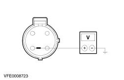
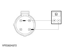
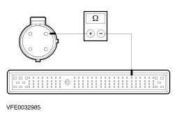
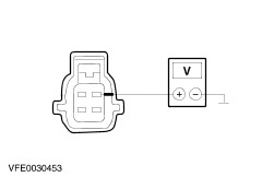
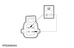
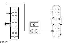
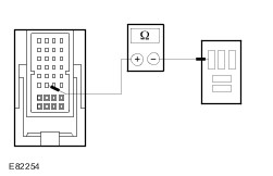
- Check the normally open contact in the switched state.
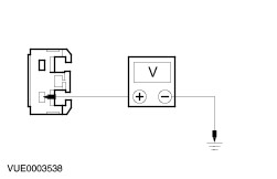
- Use a fused test cable (1 A) to connect pin 1 of the air conditioning clutch relay, component side, to the battery positive terminal.
- Use a test cable to connect pin 2 of the air conditioning clutch relay, component side, to the battery negative terminal.
- Measure the resistance at the air conditioning clutch relay, between pin 3 and pin 5, component side.
- Is a resistance of less than 2 Ohm registered?
1. If yes, then the air conditioning clutch relay is OK. 2. If no, RENEW the air conditioning clutch relay. |