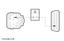
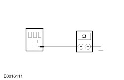
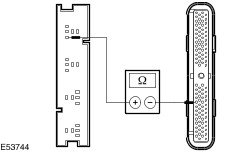
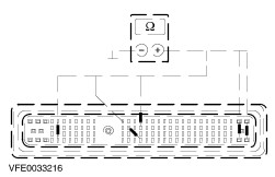
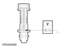
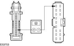
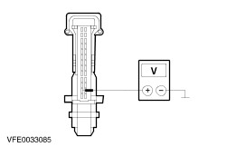
| Diagnosis and Testing Refer to Wiring Diagrams Section 418-00, for schematic and connector information. Special Tool(s) | | Terminal Probe Kit 418-S035 | General Equipment Digital Multimeter Worldwide Diagnostic System (WDS) Inspection and Testing - Visually inspect for obvious signs of mechanical or electrical damage.
Visual Inspection | Electrical | - Fuses
- Wiring harness
- Electrical connectors
| - If an obvious cause for an observed or reported concern is found, correct the cause (if possible) before proceeding to the next step. CHECK the operation of the system.
- If the concern persists after the visual inspection, PERFORM a fault diagnosis with WDS and RECTIFY any displayed faults in accordance with the displayed fault description. CHECK operation of system.
- For vehicles with no stored fault(s), PROCEED in accordance with the symptom chart according to the fault symptom.
- Following checking or elimination of the fault and after completion of operations, the fault memories of all vehicle modules must be READ OUT and any stored faults must be DELETED. READ OUT the fault memory of all modules again after a road test.
Symptom Chart Symptom Chart NOTE:The central timer module (CTM) is integrated in the instrument cluster. | Symptom | Possible Sources | Action | | Safety restraint control module (RCM) not communicating with the diagnostic unit | * Fuse(s) * Circuit(s) * Restraints control module (RCM). | * | | ABS module not communicating with the diagnostic unit | * Fuse(s) * Circuit(s) * ABS module. | * | | Powertrain control module (PCM) not communicating with the diagnostic unit | * Fuse(s) * Circuit(s) * Powertrain control module (PCM). | * | | Fuel-fired additional heater not communicating with the diagnostic unit | * Fuse(s) * Circuit(s) * Fuel-fired booster heater. | * | | Parking aid module not communicating with the diagnostic unit | * Fuse(s) * Circuit(s) * Parking aid module. | * | | Door locking module not communicating with the diagnostic unit | * Fuse(s) * Circuit(s) * Door locking module. | * | | Instrument cluster or central timer module (CTM) not communicating with the diagnostic unit | * Fuse(s) * Circuit(s) * Instrument cluster or CTM. | * | | No communications possible via the ISO 9141 bus | * Fuse(s) * Circuitry. * ABS module. * Fuel-fired booster heater. * Parking aid module. * Door locking module. * Safety restraint control module (RCM) | * | | No communications possible via the SCP bus | * Fuse(s) * Circuitry. * Instrument cluster * PCM | * | System tests | PINPOINT TEST A : SAFETY RESTRAINT CONTROL MODULE (RCM) NOT COMMUNICATING WITH THE DIAGNOSTIC UNIT | WARNING:The stored voltage must be discharged in order to prevent unintentional deployment of the airbag/belt pretensioner. After disconnecting the battery, wait at least 1 minute before starting work on the safety restraint system (SRS). Failure to observe this instruction can lead to injury. | WARNING:Do not program any keycodes while working on the safety restraint system in order to prevent the risk of accidental deployment of safety restraint system components. Failure to observe this instruction can lead to injury. | WARNING:Never use terminal probes to test any connectors of the airbag systems or of any other safety restraint systems. Failure to observe this instruction can lead to injury. | | TEST CONDITIONS | DETAILS/RESULTS/ACTIONS | | A1: CHECK FUSE F10 | | | 1 Ignition switch in position 0. | | | 2 CHECK fuse F10 (BJB). | | | Is the fuse OK? Yes No INSTALL A NEW fuse F10 (10 A). CHECK operation of system. If the fuse blows again, LOCATE and REPAIR the short using the Wiring Diagrams. | | A2: CHECK THE VOLTAGE AT FUSE F10 | | | 1 Connect fuse F10 (BJB). | | | 2 Measure the voltage between fuse F10 (10 A) and ground. | | | Is battery voltage measured? Yes No REPAIR the voltage supply to fuse F10 using the Wiring Diagrams. CHECK operation of system. | | A3: CHECK THE VOLTAGE AT THE DATA LINK CONNECTOR (DLC) | | | 1 Measure the voltage between the DLC, connector C200, pin 16, circuit 30-RA1 (RD), wiring harness side and ground. | | | Is battery voltage measured? Yes No LOCATE and REPAIR the break in the circuit between the DLC and fuse F10 using the Wiring Diagrams. CHECK operation of system. | | A4: CHECK THE GROUND CONNECTION OF THE DLC (PIN 4) | | | 1 Measure the resistance between the DLC, connector C200, pin 4, circuit 31-RA1 (BK), wiring harness side and ground. | | | Is a resistance of less than 2 Ohms registered? Yes No LOCATE and RECTIFY the break in the circuit between the DLC and ground connection G14 with the aid of the Wiring Diagrams. CHECK system operates correctly | | A5: CHECK THE GROUND CONNECTION OF THE DLC (PIN 5) | | | 1 Measure the resistance between the DLC, connector C200, pin 5, circuit 91-RA1 (BK/OG), wiring harness side and ground. | | | Is a resistance of less than 2 Ohms registered? Yes No LOCATE and RECTIFY the break in the circuit between the DLC and ground connection G41 with the aid of the Wiring Diagrams. CHECK system operates correctly | | A6: CHECK FUSE F63 | | | 1 CHECK Fuse F63 (CJB). | | | Is the fuse OK? Yes No Install a new fuse F63 (20 A). CHECK system operates correctly If the fuse blows again, LOCATE and REPAIR the short using the Wiring Diagrams. | | A7: CHECK THE VOLTAGE AT FUSE F63 | | | 1 Connect Fuse F63 (CJB). | | | 2 Measure the voltage between fuse F63 (20 A) and ground. | | | Is battery voltage measured? Yes No REPAIR the voltage supply to fuse F63 with the aid of the Wiring Diagrams. CHECK operation of system. | | A8: CHECK FUSE F38 | | | 1 CHECK fuse F38 (CJB). | | | Is the fuse OK? Yes No INSTALL A NEW fuse F38 (7.5 A). CHECK system operates correctly If the fuse blows again, LOCATE and REPAIR the short using the Wiring Diagrams. | | A9: CHECK THE VOLTAGE AT FUSE F38 | | | 1 Connect fuse F38 (CJB). | | | 2 Ignition switch in position II. | | | 3 Measure the voltage between fuse F38 (7.5 A) and ground. | | | Is battery voltage measured? Yes No REPAIR the voltage supply to fuse F38 using the Wiring Diagrams. CHECK operation of system. | | A10: CHECK THE VOLTAGE AT THE RCM | NOTE:After connecting the battery, initialize the power window motors. | | | 1 Ignition switch in position 0. | | | 2 Disconnect Battery ground cable. | | | 3 Disconnect connector C451 from RCM. | | | 4 Disconnect connector C424 from RCM. | | | 5 Connect Battery ground cable. | | | 6 Measure the voltage between the RCM, connector C451, pin 5, circuit 29-AA17 (OG/WH), wiring harness side and ground. | | | Is battery voltage measured? Yes No | | A11: CHECK FOR OPEN CIRCUIT BETWEEN THE CJB AND THE RCM | | | 1 Disconnect connector C13 from CJB. | | | 2 Measure the resistance between the CJB, connector C13, pin 4, circuit 29-AA17 (OG/WH), wiring harness side and the RCM, connector C451, pin 5, circuit 29-AA17 (OG/WH), wiring harness side. | | | Is a resistance of less than 2 Ohms registered? Yes CHECK the CJB and RENEW as necessary. CHECK operation of system. No LOCATE and REPAIR the open circuit in 29-AA17 (OG/WH) between the RCM and the CJB using the Wiring Diagrams. CHECK operation of system. | | A12: CHECK THE VOLTAGE AT THE RCM | | | 1 Ignition switch in position II. | | | 2 Measure the voltage between RCM, connector C424, pin 8, circuit 15-JA10 (GN/OG), wiring harness side and ground. | | | Is battery voltage measured? Yes No | | A13: CHECK FOR OPEN CIRCUIT BETWEEN THE CJB AND THE RCM | | | 1 Ignition switch in position 0. | | | 2 Disconnect connector C15 from CJB. | | | 3 Measure the resistance between the CJB, connector C15, pin 8, circuit 15-JA10 (GN/OG), wiring harness side and the RCM, connector C424, pin 8, circuit 15-JA10 (GN/OG), wiring harness side. | | | Is a resistance of less than 2 Ohms registered? Yes CHECK the CJB and RENEW as necessary. CHECK system operates correctly No LOCATE and REPAIR the open circuit in 15-JA10 (GN/OG) between the RCM and the CJB using the Wiring Diagrams. CHECK system operates correctly | | A14: CHECK THE GROUND CONNECTION OF THE RCM | | | 1 Ignition switch in position 0. | | | 2 Measure the resistance between the RCM, connector C424, pin 9, circuit 91-JA10 (BK/RD), wiring harness side and ground. | | | Is a resistance of less than 2 Ohms registered? Yes No LOCATE and RECTIFY the break in circuit 91-JA10 (BK/RD) between the RCM and ground connection G59 with the aid of the Wiring Diagrams. CHECK system operates correctly | | A15: CHECK FOR OPEN CIRCUIT BETWEEN THE RCM AND THE DLC | CAUTION:The following measurement may only be performed using the WDS digital multimeter. Failure to observe this instruction can lead to damage. | | | 1 Measure the resistance between the RCM, connector C424, pin 7, circuit 8-EE7 (WH/RD), wiring harness side and the DLC, connector C200, pin 7, circuit 8-EE10 (WH/BK), wiring harness side. | | | Is a resistance of less than 2 Ohms registered? Yes No LOCATE and RECTIFY the break in circuit 8-EE7 (WH/RD) between the RCM and soldered connection S10 with the aid of the Wiring Diagrams. CHECK operation of system. | | PINPOINT TEST B : ABS MODULE NOT COMMUNICATING WITH THE DIAGNOSTIC UNIT | | TEST CONDITIONS | DETAILS/RESULTS/ACTIONS | | B1: DETERMINE THE CONDITIONS UNDER WHICH THE FAULT OCCURS | | | 1 Ignition switch in position 0. | | | 2 Connect the diagnostic tool. | | | 3 Select the safety restraint control module (RCM) with the diagnostic tester. | | | Is it possible to establish communication with the safety restraint control module (RCM)? Yes No | | B2: CHECK FUSE F23 | | | 1 CHECK fuse F23 (BJB). | | | Is the fuse OK? Yes No INSTALL a new fuse F23 (20 A). CHECK operation of system. If the fuse blows again, LOCATE and REPAIR the short using the Wiring Diagrams. | | B3: CHECK THE VOLTAGE AT FUSE F23 | | | 1 Connect fuse F23 (BJB). | | | 2 Measure the voltage between fuse F23 (20 A) and ground. | | | Is battery voltage measured? Yes No REPAIR the voltage supply to fuse F23 using the Wiring Diagrams. CHECK operation of system. | | B4: CHECK FUSE F13 | | | 1 CHECK Fuse F13 (BJB). | | | Is the fuse OK? Yes No INSTALL a new fuse F13 (30 A). CHECK operation of system. If the fuse blows again, LOCATE and REPAIR the short using the Wiring Diagrams. | | B5: CHECK THE VOLTAGE AT FUSE F13 | | | 1 Connect Fuse F13 (BJB). | | | 2 Measure the voltage between fuse F13 (30 A) and ground. | | | Is battery voltage measured? Yes No REPAIR the voltage supply to fuse F13 using the Wiring Diagrams. CHECK operation of system. | | B6: CHECK FUSE F36 | | | 1 CHECK fuse F36 (CJB). | | | Is the fuse OK? Yes No RENEW fuse F36 (7.5 A). CHECK operation of system. If the fuse blows again, LOCATE and REPAIR the short using the Wiring Diagrams. | | B7: CHECK THE VOLTAGE AT FUSE F36 | | | 1 Connect fuse F36 (CJB). | | | 2 Ignition switch in position II. | | | 3 Measure the voltage between fuse F36 (7.5 A) and ground. | | | Is battery voltage measured? Yes No REPAIR the voltage supply to fuse F36 using the Wiring Diagrams. CHECK operation of system. | | B8: CHECK THE VOLTAGE AT THE ABS MODULE | | | 1 Ignition switch in position 0. | | | 2 Disconnect Connector C830 of the ABS module. | | | 3 Measure voltage between the ABS module, connector C830, pin 32, circuit 30-CF6A (RD), wiring harness side and ground. | | | Is battery voltage measured? Yes No LOCATE and REPAIR the break in the circuit between the ABS module and fuse F23 using the wiring diagrams. CHECK operation of system. | | B9: CHECK THE VOLTAGE AT THE ABS MODULE | | | 1 Measure voltage between the ABS module, connector C830, pin 1, circuit 30-CF13A (RD), wiring harness side and ground. | | | Is battery voltage measured? Yes No LOCATE and REPAIR the break in the circuit between the ABS module and fuse F13 using the wiring diagrams. CHECK operation of system. | | B10: CHECK THE VOLTAGE AT THE ABS MODULE | | | 1 Ignition switch in position II. | | | 2 Measure the voltage between the ABS module, connector C830, pin 4, circuit 15-CF6A (GN/YE), wiring harness side and ground. | | | Is battery voltage measured? Yes No | | B11: CHECK CIRCUIT BETWEEN THE ABS MODULE AND CJB FOR OPEN CIRCUIT | | | 1 Ignition switch in position 0. | | | 2 Disconnect connector C10 from CJB. | | | 3 Measure the resistance between the CJB, connector C10, pin 2, circuit 15-CF6 (GN/YE), wiring harness side and the ABS module, connector C830, pin 4, circuit 15-CF6A (GN/YE), wiring harness side. | | | Is a resistance of less than 2 Ohms registered? Yes CHECK the CJB and RENEW as necessary. CHECK operation of system. No LOCATE and REPAIR the break in the circuit between the ABS module and CJB using the wiring diagrams. CHECK operation of system. | | B12: CHECK THE GROUND CONNECTION OF THE ABS MODULE | | | 1 Ignition switch in position 0. | | | 2 Measure the resistance between the ABS module, connector C830, pin 16, circuit 91-CF6 (BK/YE), wiring harness side and ground. | | | 3 Measure the resistance between the ABS module, connector C830, pin 47, circuit 91-CF13 (BK/YE), wiring harness side and ground. | | | Is a resistance of less than 2 Ohms measured in both cases? Yes No - If a resistance of more than 2 Ohms is measured in one of the measurements:LOCATE and REPAIR the break in the relevant circuit between the ABS module and soldered connection S141 using the Wiring Diagrams. CHECK operation of system. - If a resistance greater than 2 Ohms is measured in both cases:LOCATE and REPAIR the open in circuit between solder point S141 and ground G55, by using the wiring diagrams. CHECK operation of system. | | B13: CHECK THE CIRCUIT BETWEEN THE ABS MODULE AND THE DATA LINK CONNECTOR (DLC) FOR OPEN CIRCUIT | CAUTION:The following measurement may only be performed using the WDS digital multimeter. Failure to observe this instruction can lead to damage. | | | 1 Measure the resistance between the ABS module, connector C830, pin 2, circuit 8-EE6A (WH), wiring harness side and the DLC, connector C200, pin 7, circuit 8-EE10 (WH/BK), wiring harness side. | | | Is a resistance of less than 2 Ohms registered? Yes CHECK the ABS module and if necessary INSTALL a new one. CHECK operation of system. No LOCATE and REPAIR the break in the circuit between the ABS module and solder point S10 using the wiring diagrams. CHECK operation of system. | | PINPOINT TEST C : POWERTRAIN CONTROL MODULE (PCM) NOT COMMUNICATING WITH THE DIAGNOSTIC UNIT | | TEST CONDITIONS | DETAILS/RESULTS/ACTIONS | | C1: CHECK FUSE F10 | | | 1 Ignition switch in position 0. | | | 2 CHECK fuse F10 (BJB). | | | Is the fuse OK? Yes No INSTALL A NEW fuse F10 (10 A). CHECK operation of system. If the fuse blows again, LOCATE and REPAIR the short using the Wiring Diagrams. | | C2: CHECK THE VOLTAGE AT FUSE F10 | | | 1 Connect fuse F10 (BJB). | | | 2 Measure the voltage between fuse F10 (10 A) and ground. | | | Is battery voltage measured? Yes No REPAIR the voltage supply to fuse F10 using the Wiring Diagrams. CHECK operation of system. | | C3: CHECK THE VOLTAGE AT THE DATA LINK CONNECTOR (DLC) | | | 1 Measure the voltage between the DLC, connector C200, pin 16, circuit 30-RA1 (RD), wiring harness side and ground. | | | Is battery voltage measured? Yes No LOCATE and REPAIR the break in the circuit between the DLC and fuse F10 using the Wiring Diagrams. CHECK operation of system. | | C4: CHECK THE GROUND CONNECTION OF THE DLC (PIN 4) | | | 1 Measure the resistance between the DLC, connector C200, pin 4, circuit 31-RA1 (BK), wiring harness side and ground. | | | Is a resistance of less than 2 Ohms registered? Yes No LOCATE and RECTIFY the break in the circuit between the DLC and ground connection G14 with the aid of the Wiring Diagrams. CHECK operation of system. | | C5: CHECK THE GROUND CONNECTION OF THE DLC (PIN 5) | | | 1 Measure the resistance between the DLC, connector C200, pin 5, circuit 91-RA1 (BK/OG), wiring harness side and ground. | | | Is a resistance of less than 2 Ohms registered? Yes - Vehicles with common rail fuel injection system: GO to C10. - Vehicles without common rail fuel injection system: GO to C6. No LOCATE and RECTIFY the break in the circuit between the DLC and ground connection G41 with the aid of the Wiring Diagrams. CHECK operation of system. | | C6: CHECK FUSE F20 | | | 1 CHECK Fuse F20 (BJB). | | | Is the fuse OK? Yes No Install a new fuse F20 (10 A). CHECK operation of system. If the fuse blows again, LOCATE and REPAIR the short using the Wiring Diagrams. | | C7: TEST THE VOLTAGE AT FUSE F20 | | | 1 Connect Fuse F20 (BJB). | | | 2 Measure the voltage between fuse F20 (10 A) and ground. | | | Is battery voltage measured? Yes - All except vehicles with diesel engines: GO to C8. No REPAIR the voltage supply to fuse F20 with the aid of the Wiring Diagrams. CHECK operation of system. | | C8: CHECK FUSE F18 | | | 1 CHECK Fuse F18 (BJB). | | | Is the fuse OK? Yes No RENEW fuse F18 (10 A). CHECK operation of system. If the fuse blows again, LOCATE and REPAIR the short using the Wiring Diagrams. | | C9: CHECK THE VOLTAGE AT FUSE F18 | | | 1 Connect Fuse F18 (BJB). | | | 2 Ignition switch in position II. | | | 3 Measure the voltage between fuse F18 (10 A) and ground. | | | Is battery voltage measured? Yes No | | C10: CHECK FUSE F9 | | | 1 Ignition switch in position 0. | | | 2 CHECK fuse F9 (BJB). | | | Is the fuse OK? Yes No RENEW fuse F9 (20 A). CHECK operation of system. If the fuse blows again, LOCATE and REPAIR the short using the Wiring Diagrams. | | C11: CHECK THE VOLTAGE AT FUSE F9 | | | 1 Connect fuse F9 (BJB). | | | 2 Measure the voltage between fuse F9 (20 A) and ground. | | | Is battery voltage measured? Yes - Vehicles with common rail fuel injection system: GO to C17. - All except vehicles with diesel engines: GO to C19. No REPAIR the voltage supply to fuse F9 using the Wiring Diagrams. CHECK operation of system. | | C12: CHECK THE VOLTAGE AT THE PCM (PIN 1) | | | 1 Ignition switch in position 0. | | | 2 Disconnect connector C416 of PCM. | | | 3 Measure the voltage between the PCM, connector C416, pin 1, circuit 30-RE8 (RD), wiring harness side and ground. | | | Is battery voltage measured? Yes No LOCATE and RECTIFY the break in circuit 30-RE8 (RD) between PCM and fuse F20 with the aid of the Wiring Diagrams. CHECK operation of system. | | C13: CHECK THE VOLTAGE AT THE PCM (PIN 37 + PIN 57) | | | 1 Ignition switch in position II. | | | 2 Measure the voltage between PCM, connector C416, pin 37, circuit 15-RE8M (GN/YE), wiring harness side and ground. | | | 3 Measure the voltage between PCM, connector C416, pin 57, circuit 15-RE8N (GN/YE), wiring harness side and ground. | | | Is battery voltage measured in both cases? Yes No - If battery voltage is not measured during one measurement:LOCATE and RECTIFY the break in the corresponding circuit between the PCM and solder point S54 with the aid of the Wiring Diagrams. CHECK operation of system. - If battery voltage is not measured during both of the measurements:LOCATE and RECTIFY the break in the corresponding circuit between the voltage supply relay and solder point S54 with the aid of the Wiring Diagrams. CHECK operation of system. | | C14: CHECK THE VOLTAGE AT THE PCM (PIN 8) | | | 1 Disconnect connector C415 of PCM. | | | 2 Ignition switch in position II. | | | 3 Measure the voltage between PCM, connector C415, pin 8, circuit 15-RE17 (GN/BU), wiring harness side and ground. | | | Is battery voltage measured? Yes No LOCATE and REPAIR the break in the circuit between the PCM and the ignition switch using the Wiring Diagrams. CHECK operation of system. | | C15: CHECK THE VOLTAGE AT THE PCM (PIN 55) | | | 1 Ignition switch in position 0. | | | 2 Measure the voltage between the PCM, connector C415, pin 55, circuit 30-RE8 (RD), wiring harness side and ground. | | | Is battery voltage measured? Yes No LOCATE and REPAIR the break in the circuit between the PCM and fuse F20 using the Wiring Diagrams. CHECK operation of system. | | C16: CHECK THE VOLTAGE AT THE PCM | | | 1 Ignition switch in position 0. | | | 2 Use a fused test lead (1 A) at the PCM, connector C415, pin 96 to bridge circuit 31S-RH10 (BK/OG), wiring harness side and ground. | | | 3 Measure the voltage between PCM, connector C415, pin 97, circuit 15-RE8A (GN/YE), wiring harness side and ground. | | | Is battery voltage measured? Yes No | | C17: CHECK THE VOLTAGE AT THE PCM (PIN 37) | | | 1 Ignition switch in position 0. | | | 2 Disconnect connector C414 of PCM. | | | 3 Ignition switch in position II. | | | 4 Measure the voltage between PCM, connector C414, pin 37, circuit 15-RE17A (GN/BU), wiring harness side and ground. | | | Is battery voltage measured? Yes No LOCATE and REPAIR the break in the circuit between the PCM and the ignition switch using the Wiring Diagrams. CHECK operation of system. | | C18: CHECK THE VOLTAGE AT THE PCM | | | 1 Ignition switch in position 0. | | | 2 Use a fused test lead (1 A) at the PCM, connector C414, pin 9 to bridge circuit 31S-RH10A (BK/OG), wiring harness side and ground. | | | 3 Measure the voltage between PCM, connector C414, pin 3, circuit 15-RE8G (GN/YE), wiring harness side and ground. | | | 4 Measure the voltage between PCM, connector C414, pin 4, circuit 15-RE8H (GN/YE), wiring harness side and ground. | | | 5 Measure the voltage between PCM, connector C414, pin 5, circuit 15-RE8J (GN/YE), wiring harness side and ground. | | | Is battery voltage measured in all cases? Yes No - Battery voltage not measured in one/two cases:LOCATE and RECTIFY the break in the corresponding circuit between the PCM and solder point S54 with the aid of the Wiring Diagrams. CHECK operation of system. - If battery voltage is not measured during all of the measurements: GO to C19. | | C19: CHECK THE VOLTAGE AT THE POWER SUPPLY RELAY | | | 1 Disconnect voltage supply relay from socket C1008. | | | 2 Measure the voltage between the power supply relay, socket C1008, pin 3, circuit 30-RH10 (RD), wiring harness side and ground. | | | Is battery voltage measured? Yes - All except vehicles with diesel engines: GO to C20. No LOCATE and REPAIR the break in circuit 30-RH10 (RD) between the power supply relay and fuse F9 using the Wiring Diagrams. CHECK operation of system. | | C20: CHECK THE VOLTAGE AT THE POWER SUPPLY RELAY | | | 1 Ignition switch in position II. | | | 2 Measure the voltage between the power supply relay, socket C1008, pin 1, circuit 15-RH9 (GN/BU), wiring harness side and ground. | | | Is battery voltage measured? Yes No LOCATE and RECTIFY the break in the circuit between the power supply relay and the ignition switch with the aid of the Wiring Diagrams. CHECK operation of system. | | C21: CHECK THE GROUND CONNECTION OF THE ENGINE MANAGEMENT RELAY | | | 1 Ignition switch in position 0. | | | 2 Measure the resistance between the power supply relay, socket C1008, pin 2, circuit 91-DA4 (BK/GN), wiring harness side and ground. | | | Is a resistance of less than 2 Ohms registered? Yes No LOCATE and RECTIFY the break in the circuit between the power supply relay and ground connection G37 with the aid of the Wiring Diagrams. CHECK operation of system. | | C22: CHECK FOR OPEN CIRCUIT BETWEEN THE POWER SUPPLY RELAY AND THE PCM | | | 1 Disconnect connector C416 of PCM. | | | 2 Measure the resistance between power supply relay, socket C1008, pin 5, circuit 15-RH10 (GN/RD) wiring harness side and PCM, connector C416, pin 37, circuit 15RE8M (BK/OG), wiring harness side. | | | Is a resistance of less than 2 Ohms registered? Yes RENEW the power supply relay. CHECK operation of system. No LOCATE and REPAIR the open circuit between the engine management relay and the PCM using the Wiring Diagrams. CHECK operation of system. | | C23: CHECK THE VOLTAGE AT THE POWER SUPPLY RELAY | | | 1 Measure the voltage between the power supply relay, socket C1008, pin 1, circuit 30-RH9 (RD), wiring harness side and ground. | | | Is battery voltage measured? Yes - Vehicles with common rail fuel injection system: GO to C26. No LOCATE and REPAIR the break in circuit 30-RH9 (RD) between the power supply relay and fuse F9 using the Wiring Diagrams. CHECK operation of system. | | C24: CHECK FOR OPEN CIRCUIT BETWEEN THE POWER SUPPLY RELAY AND THE PCM | | | 1 Measure the resistance between the power supply relay, socket C1008, pin 2, circuit 31S-RH10 (BK/OG), wiring harness side and the PCM, connector C415, pin 96, circuit 31S-RH10 (BK/OG), wiring harness side. | | | Is a resistance of less than 2 Ohms registered? Yes No LOCATE and REPAIR the break in circuit 30S-RH10 (BK/OG) between the power supply relay and the PCM using the Wiring Diagrams. CHECK operation of system. | | C25: CHECK FOR OPEN CIRCUIT BETWEEN THE POWER SUPPLY RELAY AND THE PCM | | | 1 Measure the resistance between power supply relay, socket C1008, pin 5, circuit 15-RH10 (GN/RD) wiring harness side and PCM, connector C415, pin 97, circuit 15-RE8A (GN/YE), wiring harness side. | | | Is a resistance of less than 2 Ohms registered? Yes RENEW the power supply relay. CHECK operation of system. No LOCATE and REPAIR the open circuit between the engine management relay and the PCM using the Wiring Diagrams. CHECK operation of system. | | C26: CHECK FOR OPEN CIRCUIT BETWEEN THE POWER SUPPLY RELAY AND THE PCM | | | 1 Measure the resistance between the power supply relay, socket C1008, pin 2, circuit 31S-RH10 (BK/OG), wiring harness side and the PCM, connector C414, pin 9, circuit 31S-RH10A (BK/OG), wiring harness side. | | | Is a resistance of less than 2 Ohms registered? Yes No LOCATE and REPAIR the open circuit between the engine management relay and the PCM using the Wiring Diagrams. CHECK operation of system. | | C27: CHECK FOR OPEN CIRCUIT BETWEEN THE POWER SUPPLY RELAY AND THE PCM | | | 1 Measure the resistance between power supply relay, socket C1008, pin 5, circuit 15-RH10 (GN/RD) wiring harness side and PCM, connector C414, pin 4, circuit 15-RE8H (GN/YE), wiring harness side. | | | Is a resistance of less than 2 Ohms registered? Yes RENEW the power supply relay. CHECK operation of system. No LOCATE and RECTIFY the break in the circuit between the voltage supply relay and solder point S54 with the aid of the Wiring Diagrams. CHECK operation of system. | | C28: CHECK THE GROUND CONNECTION OF THE PCM | | | 1 Ignition switch in position 0. | | | 2 Measure the resistance between the PCM, connector C416, pin 16, circuit 91-RE8M (BK/YE), wiring harness side and ground. | | | 3 Measure the resistance between the PCM, connector C416, pin 40, circuit 91-RE8N (BK/YE), wiring harness side and ground. | | | 4 Measure the resistance between the PCM, connector C416, pin 60, circuit 91-RE8P (BK/YE), wiring harness side and ground. | | | Is a resistance of less than 2 Ohms measured in all of the cases? Yes No - If a resistance of more than 2 Ohms is measured in one or two of the measurements:LOCATE and REPAIR the break in the relevant circuit between the PCM and soldered connection S53 using the Wiring Diagrams. CHECK operation of system. - Is a resistance of more than 2 Ohms measured in all of the measurements?LOCATE and RECTIFY the break in the circuit between solder point S53 and ground connection G27 with the aid of the Wiring Diagrams. CHECK operation of system. | | C29: CHECK THE GROUND CONNECTION OF THE PCM (PIN 20) | | | 1 Measure the resistance between the PCM, connector C416, pin 20, circuit 31-RE8B (BK), wiring harness side and ground. | | | Is a resistance of less than 2 Ohms registered? Yes No LOCATE and RECTIFY the open circuit in circuit 31-RE8B (BK) between the PCM and ground connection G24 with the aid of the Wiring Diagrams. CHECK operation of system. | | C30: CHECK FOR OPEN CIRCUIT BETWEEN THE PCM AND THE DLC (SCP BUS) | CAUTION:The measurements below may only be performed using the WDS digital multimeter. Failure to observe this instruction can lead to damage. | | | 1 Measure the resistance between the PCM, connector C416, pin 19, circuit 4-EG9 (vehicles built from 02/2004: 4-EG9C) (GY/OG), wiring harness side and DLC, connector C200, pin 2, circuit 4-EG7 (GY/RD), wiring harness side. | | | 2 Measure the resistance between the PCM, connector C416, pin 18, circuit 5-EG9 (vehicles built from 02/2004: 5-EG9C) (BU/BK), wiring harness side and DLC, connector C200, pin 10, circuit 5-EG7 (BU/RD), wiring harness side. | | | Is a resistance of less than 2 Ohms measured in both cases? Yes No LOCATE and REPAIR the break in the relevant circuit between the PCM and the DLC using the Wiring Diagrams. CHECK operation of system. | | C31: CHECK THE GROUND CONNECTION OF THE PCM | | | 1 Measure the resistance between the PCM, connector C415, pin 76, circuit 91-RE8E (BK/YE), wiring harness side and ground. | | | 2 Measure the resistance between the PCM, connector C415, pin 77, circuit 91-RE8 (BK/YE), wiring harness side and ground. | | | 3 Measure the resistance between the PCM, connector C415, pin 103, circuit 91-RE8C (BK/YE), wiring harness side and ground. | | | Is a resistance of less than 2 Ohms measured in all of the cases? Yes No - If a resistance of more than 2 Ohms is measured in one or two of the measurements:LOCATE and REPAIR the break in the relevant circuit between the PCM and soldered connection S53 using the Wiring Diagrams. CHECK operation of system. - Is a resistance of more than 2 Ohms measured in all of the measurements?LOCATE and RECTIFY the break in the circuit between solder point S53 and ground connection G27 with the aid of the Wiring Diagrams. CHECK operation of system. | | C32: CHECK THE GROUND CONNECTION OF THE PCM (PIN 25) | | | 1 Measure the resistance between the PCM, connector C415, pin 25, circuit 31-RE8 (BK), wiring harness side and ground. | | | Is a resistance of less than 2 Ohms registered? Yes No LOCATE and RECTIFY the open circuit in circuit 31-RE8 (BK) between the PCM and ground connection G24 with the aid of the Wiring Diagrams. CHECK operation of system. | | C33: CHECK FOR OPEN CIRCUIT BETWEEN THE PCM AND THE DLC (SCP BUS) | CAUTION:The measurements below may only be performed using the WDS digital multimeter. Failure to observe this instruction can lead to damage. | | | 1 Measure the resistance between the PCM, connector C415, pin 16, circuit 4-EG9 (GY/OG), wiring harness side and the DLC, connector C200, pin 2, circuit 4-EG7 (GY/RD), wiring harness side. | | | 2 Measure the resistance between the PCM, connector C415, pin 15, circuit 5-EG9 (BU/BK), wiring harness side and the DLC, connector C200, pin 10, circuit 5-EG7 (BU/RD), wiring harness side. | | | Is a resistance of less than 2 Ohms measured in both cases? Yes No LOCATE and REPAIR the break in the relevant circuit between the PCM and the DLC using the Wiring Diagrams. CHECK operation of system. | | C34: CHECK THE GROUND CONNECTION OF THE PCM | | | 1 Measure the resistance between the PCM, connector C414, pin 1, circuit 91-RE8G (BK/YE), wiring harness side and ground. | | | 2 Measure the resistance between the PCM, connector C414, pin 2, circuit 91-RE8H (BK/YE), wiring harness side and ground. | | | 3 Measure the resistance between the PCM, connector C414, pin 28, circuit 91-RE8J (BK/YE), wiring harness side and ground. | | | 4 Measure the resistance between the PCM, connector C414, pin 66, circuit 91-RE8K (BK/YE), wiring harness side and ground. | | | 5 Measure the resistance between the PCM, connector C414, pin 88, circuit 91-RE8L (BK/YE), wiring harness side and ground. | | | Is a resistance of less than 2 Ohms measured in all of the cases? Yes No - If a resistance of more than 2 Ohms is measured in one or more of the measurements:LOCATE and REPAIR the break in the relevant circuit between the PCM and soldered connection S53 using the Wiring Diagrams. CHECK operation of system. - Is a resistance of more than 2 Ohms measured in all of the measurements?LOCATE and RECTIFY the break in the circuit between solder point S53 and ground connection G24 with the aid of the Wiring Diagrams. CHECK operation of system. | | C35: CHECK FOR OPEN CIRCUIT BETWEEN THE PCM AND THE DLC (SCP BUS) | CAUTION:The measurements below may only be performed using the WDS digital multimeter. Failure to observe this instruction can lead to damage. | | | 1 Measure the resistance between the PCM, connector C414, pin 55, circuit 4-EG9B (GY/OG), wiring harness side and the DLC, connector C200, pin 2, circuit 4-EG7 (GY/RD), wiring harness side. | | | 2 Measure the resistance between the PCM, connector C414, pin 74, circuit 5-EG9B (BU/BK), wiring harness side and the DLC, connector C200, pin 10, circuit 5-EG7 (BU/RD), wiring harness side. | | | Is a resistance of less than 2 Ohms measured in both cases? Yes No LOCATE and REPAIR the break in the relevant circuit between the PCM and the DLC using the Wiring Diagrams. CHECK operation of system. | | PINPOINT TEST D : FUEL-FIRED ADDITIONAL HEATER NOT COMMUNICATING WITH THE DIAGNOSTIC UNIT | NOTE:The fuel fired booster heater only works when the engine is running, the battery is being charged by the generator, the ambient temperature is below 8°C and the coolant temperature has not yet exceeded 75°C. | NOTE:Ensure that the fuel-fired booster heater is switched on during fault diagnosis with WDS. If necessary, bridge the ambient temperature thermo switch. | | TEST CONDITIONS | DETAILS/RESULTS/ACTIONS | | D1: DETERMINE THE CONDITIONS UNDER WHICH THE FAULT OCCURS | | | 1 Ignition switch in position 0. | | | 2 Connect the diagnostic tool. | | | 3 Select the safety restraint control module (RCM) with the diagnostic tester. | | | Is it possible to establish communication with the safety restraint control module (RCM)? Yes No | | D2: CHECK FUSE F11 | | | 1 Ignition switch in position 0. | | | 2 CHECK Fuse F11 (BJB). | | | Is the fuse OK? Yes No Install a new fuse F11 (20 A). CHECK system operates correctly If the fuse blows again, LOCATE and REPAIR the short using the Wiring Diagrams. | | D3: CHECK THE VOLTAGE AT FUSE F11 | | | 1 Connect Fuse F11 (BJB). | | | 2 Measure the voltage between fuse F11 (20 A) and ground. | | | Is battery voltage measured? Yes No REPAIR the voltage supply to fuse F11 with the aid of the Wiring Diagrams. CHECK system operates correctly | | D4: CHECK FUSE F34 | | | 1 CHECK fuse F34 (CJB). | | | Is the fuse OK? Yes No Install a new fuse F34 (7.5 A). CHECK system operates correctly If the fuse blows again, LOCATE and REPAIR the short using the Wiring Diagrams. | | D5: CHECK THE VOLTAGE AT FUSE F34 | | | 1 Connect fuse F34 (CJB). | | | 2 Ignition switch in position II. | | | 3 Measure the voltage between fuse F34 (7.5 A) and ground. | | | Is battery voltage measured? Yes No REPAIR the voltage supply to fuse F34 with the aid of the Wiring Diagrams. CHECK system operates correctly | | D6: CHECK THE VOLTAGE AT THE FUEL FIRED ADDITIONAL HEATER | | | 1 Ignition switch in position 0. | | | 2 Disconnect Connector C878 of the fuel fired additional heater. | | | 3 Measure the voltage between the fuel fired additional heater, connector C878, pin 1, circuit 30-RD18 (RD), wiring harness side and ground. | | | Is battery voltage measured? Yes No LOCATE and RECTIFY the break in circuit 30-RD18 (RD) between the fuel fired additional heater and fuse F11 with the aid of the Wiring Diagrams. CHECK operation of system. | | D7: CHECK THE VOLTAGE AT THE FUEL FIRED ADDITIONAL HEATER | | | 1 Ignition switch in position II. | | | 2 Measure the voltage between the fuel fired additional heater, connector C878, pin 4, circuit 15-RD18 (GN/RD), wiring harness side and ground. | | | Is battery voltage measured? Yes No LOCATE and RECTIFY the break in circuit 15-RD18 (GN/RD) between the fuel fired additional heater and soldered connection S117 with the aid of the Wiring Diagrams. CHECK operation of system. | | D8: CHECK GROUND CONNECTION OF FUEL FIRED BOOSTER HEATER | | | 1 Ignition switch in position 0. | | | 2 Measure the resistance between the fuel fired additional heater, connector C878, pin 2, circuit 31-RD18 (BK), wiring harness side and ground. | | | Is a resistance of less than 2 Ohms registered? Yes No LOCATE and RECTIFY the break in circuit 31-RD18 (BK) between the fuel fired additional heater and soldered connection S121 with the aid of the Wiring Diagrams. CHECK operation of system. | | D9: CHECK THE CIRCUIT BETWEEN THE FUEL-FIRED ADDITIONAL HEATER AND THE DATA LINK CONNECTOR (DLC) FOR OPEN CIRCUIT | CAUTION:The following measurement may only be performed using the WDS digital multimeter. Failure to observe this instruction can lead to damage. | | | 1 Measure the resistance between the fuel-fired additional heater, connector C878, pin 3, circuit 8-EE11 (WH/VT), wiring harness side and the DLC, connector C200, pin 7, circuit 8-EE10 (WH/BK), wiring harness side. | | | Is a resistance of less than 2 Ohms registered? Yes CHECK and if necessary RENEW the fuel-fired additional heater. CHECK operation of system. No LOCATE and RECTIFY the break in circuit 8-EE11 (WH/VT) between the fuel-fired additional heater and soldered connection S140 with the aid of the Wiring Diagrams. CHECK operation of system. | | PINPOINT TEST E : PARKING AID MODULE NOT COMMUNICATING WITH THE DIAGNOSTIC UNIT | | TEST CONDITIONS | DETAILS/RESULTS/ACTIONS | | E1: DETERMINE THE CONDITIONS UNDER WHICH THE FAULT OCCURS | | | 1 Ignition switch in position 0. | | | 2 Connect the diagnostic tool. | | | 3 Select the safety restraint control module (RCM) with the diagnostic tester. | | | Is it possible to establish communication with the safety restraint control module (RCM)? Yes No | | E2: CHECK FUSE F48 | | | 1 CHECK Fuse F48 (CJB). | | | Is the fuse OK? Yes No INSTALL a new fuse F48 (7.5 A). CHECK operation of system. If the fuse blows again, LOCATE and REPAIR the short using the Wiring Diagrams. | | E3: CHECK THE VOLTAGE AT FUSE F48 | | | 1 Connect Fuse F48 (CJB). | | | 2 Ignition switch in position II. | | | 3 Measure the voltage between fuse F48 (7.5 A) and ground. | | | Is battery voltage measured? Yes No REPAIR the voltage supply to fuse F48 using the Wiring Diagrams. CHECK operation of system. | | E4: CHECK THE VOLTAGE AT THE PARKING AID MODULE | | | 1 Ignition switch in position 0. | | | 2 Disconnect Connector C622 of the parking aid module. | | | 3 Ignition switch in position II. | | | 4 Measure the voltage between the parking aid module, connector C622, pin 1, circuit 15-GN10 (GN/YE), wiring harness side and ground. | | | Is battery voltage measured? Yes No | | E5: CHECK CIRCUIT BETWEEN THE PARKING AID MODULE AND CJB FOR OPEN CIRCUIT | | | 1 Ignition switch in position 0. | | | 2 Disconnect connector C15 from CJB. | | | 3 Measure the resistance between the CJB, connector C15, pin 3, circuit 15-DA6 (GN/WH), wiring harness side and the parking aid module, connector C622, pin 1, circuit 15-GN10 (GN/YE), wiring harness side. | | | Is a resistance of less than 2 Ohms registered? Yes CHECK the CJB and RENEW as necessary. CHECK operation of system. No LOCATE and REPAIR the break in the circuit between the parking aid module and CJB using the wiring diagrams. CHECK operation of system. | | E6: CHECK THE GROUND CONNECTION OF THE PARKING AID MODULE | | | 1 Measure the resistance between the parking aid module, connector C622, pin 3, circuit 91-GN10 (BK/YE), wiring harness side and ground. | | | Is a resistance of less than 2 Ohms registered? Yes No LOCATE and RECTIFY the break in circuit 91-GN10 (BK/YE) between the parking aid module and soldered connection S12 with the aid of the Wiring Diagrams. CHECK operation of system. | | E7: CHECK THE CIRCUIT BETWEEN THE PARKING AID MODULE AND THE DATA LINK CONNECTOR (DLC) FOR OPEN CIRCUIT | CAUTION:The following measurement may only be performed using the WDS digital multimeter. Failure to observe this instruction can lead to damage. | | | 1 Measure the resistance between the parking aid module, connector C622, pin 5, circuit 8-EE13 (WH/RD), wiring harness side and the DLC, connector C200, pin 7, circuit 8-EE10 (WH/BK), wiring harness side. | | | Is a resistance of less than 2 Ohms registered? Yes CHECK the parking aid module if necessary INSTALL a new one. CHECK operation of system. No LOCATE and RECTIFY the break in circuit 8-EE13 (WH/RD) between the parking aid module and soldered connection S10 with the aid of the Wiring Diagrams. CHECK operation of system. | | PINPOINT TEST F : DOOR LOCKING MODULE NOT COMMUNICATING WITH THE DIAGNOSTIC UNIT | | TEST CONDITIONS | DETAILS/RESULTS/ACTIONS | | F1: DETERMINE THE CONDITIONS UNDER WHICH THE FAULT OCCURS | | | 1 Ignition switch in position 0. | | | 2 Connect the diagnostic tool. | | | 3 Select the safety restraint control module (RCM) with the diagnostic tester. | | | Is it possible to establish communication with the safety restraint control module (RCM)? Yes No | | F2: CHECK FUSE F63 | | | 1 Ignition switch in position 0. | | | 2 CHECK Fuse F63 (CJB). | | | Is the fuse OK? Yes No Install a new fuse F63 (20 A). CHECK operation of system. If the fuse blows again, LOCATE and REPAIR the short using the Wiring Diagrams. | | F3: TEST THE VOLTAGE AT FUSE F63 | | | 1 Connect Fuse F63 (CJB). | | | 2 Measure the voltage between fuse F63 (20 A) and ground. | | | Is battery voltage measured? Yes No REPAIR the voltage supply to fuse F63 using the Wiring Diagrams. CHECK operation of system. | | F4: CHECK FUSE F61 | | | 1 Ignition switch in position 0. | | | 2 CHECK Fuse F61 (CJB). | | | Is the fuse OK? Yes No INSTALL A NEW fuse F61 (15 A). CHECK operation of system. If the fuse blows again, LOCATE and REPAIR the short using the Wiring Diagrams. | | F5: CHECK THE VOLTAGE AT FUSE F61 | | | 1 Connect Fuse F61 (CJB). | | | 2 Measure the voltage between fuse F61 (15 A) and ground. | | | Is battery voltage measured? Yes No REPAIR the voltage supply to fuse F61 using the Wiring Diagrams. CHECK operation of system. | | F6: CHECK FUSE F48 | | | 1 Ignition switch in position 0. | | | 2 CHECK Fuse F48 (CJB). | | | Is the fuse OK? Yes No INSTALL a new fuse F48 (7.5 A). CHECK operation of system. If the fuse blows again, LOCATE and REPAIR the short using the Wiring Diagrams. | | F7: CHECK THE VOLTAGE AT FUSE F48 | | | 1 Connect Fuse F48 (CJB). | | | 2 Ignition switch in position II. | | | 3 Measure the voltage between fuse F48 (7.5 A) and ground. | | | Is battery voltage measured? Yes No REPAIR the voltage supply to fuse F48 using the Wiring Diagrams. CHECK operation of system. | | F8: CHECK THE VOLTAGE AT THE DOOR LOCKING MODULE | | | 1 Ignition switch in position 0. | | | 2 Disconnect connector C451 from door locking module. | | | 3 Measure the voltage between the door locking module, connector C451, pin 5, circuit 29-AA17 (OG/WH), wiring harness side and ground. | | | Is battery voltage measured? Yes No | | F9: CHECK FOR OPEN CIRCUIT BETWEEN THE CJB AND THE DOOR LOCKING MODULE | | | 1 Disconnect connector C13 from CJB. | | | 2 Measure the resistance between the CJB, connector C13, pin 4, circuit 29-AA17 (OG/WH), wiring harness side and the door locking module, connector C451, pin 5, circuit 29-AA17 (OG/WH), wiring harness side. | | | Is a resistance of less than 2 Ohms registered? Yes CHECK the CJB and RENEW as necessary. CHECK operation of system. No LOCATE and REPAIR the open circuit in 29-AA17 (OG/WH) between the door locking module and the CJB using the Wiring Diagrams. CHECK operation of system. | | F10: CHECK THE VOLTAGE AT THE DOOR LOCKING MODULE | | | 1 Measure the voltage between the door locking module, connector C451, pin 2, circuit 29-AA17A (OG/WH), wiring harness side and ground. | | | Is battery voltage measured? Yes No | | F11: CHECK FOR OPEN CIRCUIT BETWEEN THE CJB AND THE DOOR LOCKING MODULE | | | 1 Disconnect connector C14 from CJB. | | | 2 Measure the resistance between the CJB, connector C14, pin 10, circuit 29-AA17A (OG/WH), wiring harness side and the door locking module, connector C451, pin 2, circuit 29-AA17A (OG/WH), wiring harness side. | | | Is a resistance of less than 2 Ohms registered? Yes CHECK the CJB and RENEW as necessary. CHECK operation of system. No LOCATE and REPAIR the open circuit in 29-AA17A (OG/WH) between the door locking module and the CJB using the Wiring Diagrams. CHECK operation of system. | | F12: CHECK THE VOLTAGE AT THE DOOR LOCKING MODULE | | | 1 Disconnect connector C452 from door locking module. | | | 2 Ignition switch in position II. | | | 3 Measure the voltage between the door locking module, connector C452, pin 7, circuit 15-AA17 (GN/WH), wiring harness side and ground. | | | Is battery voltage measured? Yes No | | F13: CHECK FOR OPEN CIRCUIT BETWEEN THE CJB AND THE DOOR LOCKING MODULE | | | 1 Ignition switch in position 0. | | | 2 Disconnect connector C15 from CJB. | | | 3 Measure the resistance between the CJB, connector C15, pin 3, circuit 15-DA6 (GN/WH), wiring harness side and the door locking module, connector C452, pin 7, circuit 15-AA17 (GN/WH), wiring harness side. | | | Is a resistance of less than 2 Ohms registered? Yes CHECK the CJB and RENEW as necessary. CHECK operation of system. No LOCATE and REPAIR the break in the circuit between the door lock module and the CJB using the Wiring Diagrams. CHECK operation of system. | | F14: CHECK THE GROUND CONNECTION OF THE DOOR LOCKING MODULE | | | 1 Ignition switch in position 0. | | | 2 Measure the resistance between the door locking module, connector C451, pin 6, circuit 31-AA17 (BK), wiring harness side and ground. | | | Is a resistance of less than 2 Ohms registered? Yes No LOCATE and RECTIFY the break in the circuit between the door lock module and ground connection G15 with the aid of the Wiring Diagrams. CHECK operation of system. | | F15: CHECK THE CIRCUIT BETWEEN THE DOOR LOCKING MODULE AND THE DATA LINK CONNECTOR (DLC) FOR OPEN CIRCUIT | CAUTION:The following measurement may only be performed using the WDS digital multimeter. Failure to observe this instruction can lead to damage. | | | 1 Measure the resistance between the door locking module, connector C451, pin 11, circuit 8-EE9 (WH/GN), wiring harness side and the DLC, connector C200, pin 7, circuit 8-EE10 (WH/BK), wiring harness side. | | | Is a resistance of less than 2 Ohms registered? Yes CHECK and if necessary RENEW the door locking module. CHECK operation of system. No LOCATE and RECTIFY the break in circuit 8-EE9 (WH/GN) between the door locking module and soldered connection S10 with the aid of the Wiring Diagrams. CHECK system operates correctly | | PINPOINT TEST G : INSTRUMENT CLUSTER NOT COMMUNICATING WITH THE DIAGNOSTIC UNIT | | TEST CONDITIONS | DETAILS/RESULTS/ACTIONS | | G1: DETERMINE THE CONDITIONS UNDER WHICH THE FAULT OCCURS | | | 1 Ignition switch in position 0. | | | 2 Connect the diagnostic tool. | | | 3 Select the powertrain control module (PCM) with the diagnostic tester. | | | Is it possible to establish communication with the PCM? Yes No | | G2: CHECK FUSE F20 | | | 1 Ignition switch in position 0. | | | 2 CHECK Fuse F20 (BJB). | | | Is the fuse OK? Yes No Install a new fuse F20 (10 A). CHECK operation of system. If the fuse blows again, LOCATE and REPAIR the short using the Wiring Diagrams. | | G3: TEST THE VOLTAGE AT FUSE F20 | | | 1 Connect Fuse F20 (BJB). | | | 2 Measure the voltage between fuse F20 (10 A) and ground. | | | Is battery voltage measured? Yes No REPAIR the voltage supply to fuse F20 with the aid of the Wiring Diagrams. CHECK operation of system. | | G4: CHECK FUSE F40 | | | 1 CHECK Fuse F40 (CJB). | | | Is the fuse OK? Yes No Install a new fuse F40 (7.5 A). CHECK operation of system. If the fuse blows again, LOCATE and REPAIR the short using the Wiring Diagrams. | | G5: TEST THE VOLTAGE AT FUSE F40 | | | 1 Connect Fuse F40 (CJB). | | | 2 Ignition switch in position I. | | | 3 Measure the voltage between fuse F40 (7.5 A) and ground. | | | Is battery voltage measured? Yes No REPAIR the voltage supply to fuse F40 with the aid of the Wiring Diagrams. CHECK operation of system. | | G6: CHECK FUSE F48 | | | 1 Ignition switch in position 0. | | | 2 CHECK Fuse F48 (CJB). | | | Is the fuse OK? Yes No INSTALL a new fuse F48 (7.5 A). CHECK operation of system. If the fuse blows again, LOCATE and REPAIR the short using the Wiring Diagrams. | | G7: CHECK THE VOLTAGE AT FUSE F48 | | | 1 Connect Fuse F48 (CJB). | | | 2 Ignition switch in position II. | | | 3 Measure the voltage between fuse F48 (7.5 A) and ground. | | | Is battery voltage measured? Yes No REPAIR the voltage supply to fuse F48 using the Wiring Diagrams. CHECK operation of system. | | G8: CHECK THE VOLTAGE AT THE INSTRUMENT CLUSTER | | | 1 Ignition switch in position 0. | | | 2 Disconnect connector C809 of instrument cluster. | | | 3 Measure the voltage between the instrument cluster, connector C809, pin 14, circuit 30-GG14 (RD), wiring harness side and ground. | | | Is battery voltage measured? Yes No LOCATE and RECTIFY the break in circuit 30-GG14 (RD) between the instrument cluster and fuse F20 with the aid of the Wiring Diagrams. CHECK operation of system. | | G9: CHECK THE VOLTAGE AT THE INSTRUMENT CLUSTER | | | 1 Ignition switch in position I. | | | 2 Measure the voltage between the instrument cluster, connector C809, pin 10, circuit 75-GG14 (YE/BU), wiring harness side and ground. | | | Is battery voltage measured? Yes No | | G10: CHECK FOR OPEN CIRCUIT BETWEEN THE CJB AND THE INSTRUMENT CLUSTER | | | 1 Ignition switch in position 0. | | | 2 Disconnect connector C15 from CJB. | | | 3 Measure the resistance between the CJB, connector C15, pin 15, circuit 75-GG14 (YE/BU), wiring harness side and instrument cluster, connector C809, Pin 10, circuit 75-GG14 (YE/BU), wiring harness side. | | | Is a resistance of less than 2 Ohms registered? Yes CHECK the CJB and RENEW as necessary. CHECK operation of system. No LOCATE and RECTIFY the break in circuit 75-GG14 (YE/BU) between the instrument cluster and CJB with the aid of the Wiring Diagrams. CHECK operation of system. | | G11: CHECK THE VOLTAGE AT THE INSTRUMENT CLUSTER | | | 1 Ignition switch in position II. | | | 2 Measure the voltage between the instrument cluster, connector C809, pin 16, circuit 15-GG14 (GN/RD), wiring harness side and ground. | | | Is battery voltage measured? Yes No | | G12: CHECK FOR OPEN CIRCUIT BETWEEN THE CJB AND THE INSTRUMENT CLUSTER | | | 1 Ignition switch in position 0. | | | 2 Disconnect connector C15 from CJB. | | | 3 Measure the resistance between the CJB, connector C15, pin 10, circuit 15-GG14 (GN/RD), wiring harness side and instrument cluster, connector C809, Pin 16, circuit 15-GG14 (GN/RD), wiring harness side. | | | Is a resistance of less than 2 Ohms registered? Yes CHECK the CJB and RENEW as necessary. CHECK operation of system. No LOCATE and RECTIFY the break in circuit 15-GG14 (GN/RD) between the instrument cluster and CJB with the aid of the Wiring Diagrams. CHECK operation of system. | | G13: CHECK THE GROUND CONNECTION OF THE INSTRUMENT CLUSTER | | | 1 Ignition switch in position 0. | | | 2 Measure the resistance between the instrument cluster, connector C809, pin 2, circuit 91-GG14 (BK/OG), wiring harness side and ground. | | | Is a resistance of less than 2 Ohms registered? Yes No LOCATE and REPAIR the open in circuit between instrument cluster and ground G41, by using the wiring diagrams. CHECK operation of system. | | G14: CHECK THE CIRCUIT BETWEEN THE INSTRUMENT CLUSTER AND THE DATA LINK CONNECTOR (DLC) FOR OPEN CIRCUIT | CAUTION:The following measurement may only be performed using the WDS digital multimeter. Failure to observe this instruction can lead to damage. | | | 1 Measure the resistance between the instrument cluster, connector C809, pin 13, circuit 4-EG8 (GY/VT), wiring harness side and the DLC, connector C200, pin 2, circuit 4-EG7 (GY/RD), wiring harness side. | | | Is a resistance of less than 2 Ohms registered? Yes No LOCATE and REPAIR the break in the circuit between the instrument cluster and the DLC using the Wiring Diagrams. CHECK operation of system. | | G15: CHECK THE CIRCUIT BETWEEN THE INSTRUMENT CLUSTER AND THE DATA LINK CONNECTOR (DLC) FOR OPEN CIRCUIT | CAUTION:The following measurement may only be performed using the WDS digital multimeter. Failure to observe this instruction can lead to damage. | | | 1 Measure the resistance between the instrument cluster, connector C809, pin 26, circuit 5-EG8 (BU/WH), wiring harness side and the DLC, connector C200, pin 10, circuit 5-EG7 (BU/RD), wiring harness side. | | | Is a resistance of less than 2 Ohms registered? Yes CHECK and if necessary RENEW the instrument cluster. CHECK operation of system. No LOCATE and REPAIR the break in the circuit between the instrument cluster and the DLC using the Wiring Diagrams. CHECK operation of system. | | PINPOINT TEST H : NO COMMUNICATIONS POSSIBLE VIA THE ISO 9141 BUS | CAUTION:The measurements below may only be performed using the WDS digital multimeter. Failure to observe this instruction can lead to damage. | | TEST CONDITIONS | DETAILS/RESULTS/ACTIONS | | H1: CHECK FUSE F10 | | | 1 Ignition switch in position 0. | | | 2 CHECK fuse F10 (BJB). | | | Is the fuse OK? Yes No INSTALL A NEW fuse F10 (10 A). CHECK operation of system. If the fuse blows again, LOCATE and REPAIR the short using the Wiring Diagrams. | | H2: CHECK THE VOLTAGE AT FUSE F10 | | | 1 Connect fuse F10 (BJB). | | | 2 Measure the voltage between fuse F10 (10 A) and ground. | | | Is battery voltage measured? Yes No REPAIR the voltage supply to fuse F10 using the Wiring Diagrams. CHECK operation of system. | | H3: CHECK THE VOLTAGE AT THE DATA LINK CONNECTOR (DLC) | | | 1 Measure the voltage between the DLC, connector C200, pin 16, circuit 30-RA1 (RD), wiring harness side and ground. | | | Is battery voltage measured? Yes No LOCATE and REPAIR the break in the circuit between the DLC and fuse F10 using the Wiring Diagrams. CHECK operation of system. | | H4: CHECK THE GROUND CONNECTION OF THE DLC | | | 1 Measure the resistance between the DLC, connector C200, pin 4, circuit 31-RA1 (BK), wiring harness side and ground. | | | Is a resistance of less than 2 Ohms registered? Yes No LOCATE and RECTIFY the break in the circuit between the DLC and ground connection G14 with the aid of the Wiring Diagrams. CHECK operation of system. | | H5: CHECK THE GROUND CONNECTION OF THE DLC | | | 1 Measure the resistance between the DLC, connector C200, pin 5, circuit 91-RA1 (BK/OG), wiring harness side and ground. | | | Is a resistance of less than 2 Ohms registered? Yes No LOCATE and REPAIR the break in circuit 91-RA1 (BK/OG) between the DLC and ground connection G41 using the Wiring Diagrams. CHECK operation of system. | | H6: PERFORM NETWORK TEST | NOTE:The number of modules connected to the ISO 9141 bus depends on the vehicle equipment level. Therefore not every vehicle will have all the modules mentioned below. | | | 1 Connect the diagnostic tool. | | | 2 Disconnect a listed component, then perform the following test step: - Fuel-fired booster heater 878
| | | 3 Select the vehicle with the diagnostic tester. | | | Is it possible to establish communication with the restraint control module (RCM)? Yes The component disconnected last is the cause of the concern, CHECK component and if necessary RENEW. CHECK operation of system. No - If not all the listed components are disconnected:Key in the OFF position. DISCONNECT the next component (go to test step 3). - If all the listed components are disconnected: GO to H7. | | H7: CHECK FOR OPEN CIRCUIT BETWEEN THE SAFETY RESTRAINT CONTROL MODULE (RCM) AND THE DATA LINK CONNECTOR (DLC) | WARNING:The stored voltage must be discharged in order to prevent unintentional deployment of the airbag/belt pretensioner. After disconnecting the battery, wait at least 1 minute before starting work on the safety restraint system (SRS). Failure to observe this instruction can lead to injury. | WARNING:Do not program any keycodes while working on the safety restraint system in order to prevent the risk of accidental deployment of safety restraint system components. Failure to observe this instruction can lead to injury. | WARNING:Never use terminal probes to test any connectors of the airbag systems or of any other safety restraint systems. Failure to observe this instruction can lead to injury. | NOTE:After connecting the battery, initialize the power window motors. | | | 1 Disconnect Battery ground cable. | | | 2 Disconnect Connector C424 from restraints control module (RCM). | | | 3 Connect Battery ground cable. | | | 4 Measure the resistance between the restraints control module (RCM), connector C424, pin 7, circuit 8-EE7 (WH/RD), wiring harness side and the DLC, connector C200, pin 7, circuit 8-EE10 (WH/BK), wiring harness side. | | | Is a resistance of less than 2 Ohms registered? Yes No LOCATE and REPAIR the break in circuit 8-EE10 (WH/BK) between the DLC and soldered connection S10 using the Wiring Diagrams. CHECK operation of system. | | H8: TEST THE ISO 9141 BUS FOR A SHORT TO VOLTAGE | | | 1 Ignition switch in position II. | | | 2 Measure the voltage between the DLC, connector C200, pin 7, circuit 8-EE10 (WH/BK), wiring harness side and ground. | | | Is a voltage registered? Yes LOCATE and RECTIFY the short to voltage supply in the circuits connected to soldered connection S10 with the aid of the Wiring Diagrams. CHECK system operates correctly No | | H9: CHECK THE ISO 9141 BUS FOR A SHORT TO GROUND | | | 1 Ignition switch in position 0. | | | 2 Measure the resistance between the DLC, connector C200, pin 7, circuit 8-EE10 (WH/BK), wiring harness side and ground. | | | Is a resistance of more than 10,000 Ohm measured? Yes CHECK and if necessary RENEW the restraint control module (RCM). CHECK system operates correctly No LOCATE and RECTIFY the short to ground in the circuits connected to soldered connection S10 with the aid of the Wiring Diagrams. CHECK system operates correctly | | PINPOINT TEST I : NO COMMUNICATIONS POSSIBLE VIA THE SCP BUS | CAUTION:The measurements below may only be performed using the WDS digital multimeter. Failure to observe this instruction can lead to damage. | | TEST CONDITIONS | DETAILS/RESULTS/ACTIONS | | I1: CHECK FUSE F10 | | | 1 Ignition switch in position 0. | | | 2 CHECK fuse F10 (BJB). | | | Is the fuse OK? Yes No INSTALL A NEW fuse F10 (10 A). CHECK operation of system. If the fuse blows again, LOCATE and REPAIR the short using the Wiring Diagrams. | | I2: CHECK THE VOLTAGE AT FUSE F10 | | | 1 Connect fuse F10 (BJB). | | | 2 Measure the voltage between fuse F10 (10 A) and ground. | | | Is battery voltage measured? Yes No REPAIR the voltage supply to fuse F10 using the Wiring Diagrams. CHECK operation of system. | | I3: CHECK THE VOLTAGE AT THE DATA LINK CONNECTOR (DLC) | | | 1 Measure the voltage between the DLC, connector C200, pin 16, circuit 30-RA1 (RD), wiring harness side and ground. | | | Is battery voltage measured? Yes No LOCATE and REPAIR the break in the circuit between the DLC and fuse F10 using the Wiring Diagrams. CHECK operation of system. | | I4: CHECK THE GROUND CONNECTION OF THE DLC | | | 1 Measure the resistance between the DLC, connector C200, pin 4, circuit 31-RA1 (BK), wiring harness side and ground. | | | Is a resistance of less than 2 Ohms registered? Yes No LOCATE and RECTIFY the break in the circuit between the DLC and ground connection G14 with the aid of the Wiring Diagrams. CHECK operation of system. | | I5: CHECK THE GROUND CONNECTION OF THE DLC | | | 1 Measure the resistance between the DLC, connector C200, pin 5, circuit 91-RA1 (BK/OG), wiring harness side and ground. | | | Is a resistance of less than 2 Ohms registered? Yes No LOCATE and RECTIFY the break in the circuit between the DLC and ground connection G41 with the aid of the Wiring Diagrams. CHECK operation of system. | | I6: PERFORM NETWORK TEST | | | 1 Connect the diagnostic tool. | | | 2 Disconnect connector C809 from the instrument cluster, then perform the following test step: | | | 3 Select the vehicle with the diagnostic tester. | | | Is it possible to establish communication with the PCM? Yes CHECK and if necessary RENEW the instrument cluster. CHECK operation of system. No - All except vehicles with diesel engines: GO to I7. - Vehicles with direct injection: GO to I8. - Vehicles with common rail fuel injection system: GO to I9. | | I7: CHECK FOR OPEN CIRCUIT BETWEEN THE PCM AND THE DLC (SCP BUS) | | | 1 Ignition switch in position 0. | | | 2 Disconnect connector C416 of PCM. | | | 3 Measure the resistance between the PCM, connector C416, pin 19, circuit 4-EG9 (vehicles built from 02/2004: 4-EG9C) (GY/OG), wiring harness side and DLC, connector C200, pin 2, circuit 4-EG7 (GY/RD), wiring harness side. | | | 4 Measure the resistance between the PCM, connector C416, pin 18, circuit 5-EG9 (vehicles built from 02/2004: 5-EG9C) (BU/BK), wiring harness side and DLC, connector C200, pin 10, circuit 5-EG7 (BU/RD), wiring harness side. | | | Is a resistance of less than 2 Ohms measured in both cases? Yes No Break in the corresponding circuit between DLC and connector C61a (vehicles built from 02/2004: C63), LOCATE AND REPAIR THE FAULT with the aid of the Wiring Diagrams. CHECK operation of system. | | I8: CHECK FOR OPEN CIRCUIT BETWEEN THE PCM AND THE DLC (SCP BUS) | | | 1 Ignition switch in position 0. | | | 2 Disconnect connector C415 of PCM. | | | 3 Measure the resistance between the PCM, connector C415, pin 16, circuit 4-EG9 (GY/OG), wiring harness side and the DLC, connector C200, pin 2, circuit 4-EG7 (GY/RD), wiring harness side. | | | 4 Measure the resistance between the PCM, connector C415, pin 15, circuit 5-EG9 (BU/BK), wiring harness side and the DLC, connector C200, pin 10, circuit 5-EG7 (BU/RD), wiring harness side. | | | Is a resistance of less than 2 Ohms measured in both cases? Yes No Break in the corresponding circuit between DLC and connector C61a (vehicles built from 02/2004: C63), LOCATE AND REPAIR THE FAULT with the aid of the Wiring Diagrams. CHECK operation of system. | | I9: CHECK FOR OPEN CIRCUIT BETWEEN THE PCM AND THE DLC (SCP BUS) | | | 1 Ignition switch in position 0. | | | 2 Disconnect connector C414 of PCM. | | | 3 Measure the resistance between the PCM, connector C414, pin 55, circuit 4-EG9B (GY/OG), wiring harness side and the DLC, connector C200, pin 2, circuit 4-EG7 (GY/RD), wiring harness side. | | | 4 Measure the resistance between the PCM, connector C414, pin 74, circuit 5-EG9B (BU/BK), wiring harness side and the DLC, connector C200, pin 10, circuit 5-EG7 (BU/RD), wiring harness side. | | | Is a resistance of less than 2 Ohms measured in both cases? Yes No Break in the corresponding circuit between DLC and connector C61a (vehicles built from 02/2004: C63), LOCATE AND REPAIR THE FAULT with the aid of the Wiring Diagrams. CHECK operation of system. | | I10: CHECK SCP BUS FOR A SHORT CIRCUIT | | | 1 Measure the resistance between the DLC, connector C200, pin 10, circuit 5-EG7 (BU/RD) and pin 2, circuit 4-EG7 (GY/RD), wiring harness side and ground. | | | Is a resistance of more than 10,000 Ohm measured? Yes No LOCATE and REPAIR the short in the SCP bus by using the wiring diagrams. CHECK operation of system. | | I11: CHECK CIRCUIT FOR SHORT TO VOLTAGE BETWEEN THE PCM AND THE DLC (SCP BUS) | | | 1 Ignition switch in position II. | | | 2 Measure the voltage between the DLC, connector C200, pin 10, circuit 5-EG7 (BU/RD), wiring harness side and ground. | | | 3 Measure the voltage between the DLC, connector C200, pin 2, circuit 4-EG7 (GY/RD) and ground. | | | Is a voltage registered? Yes LOCATE and REPAIR the short to voltage supply in the relevant circuit between the PCM and the DLC using the Wiring Diagrams. CHECK operation of system. No | | I12: CHECK CIRCUIT FOR SHORT TO GROUND BETWEEN THE PCM AND THE DLC (SCP BUS) | | | 1 Ignition switch in position 0. | | | 2 Measure the resistance between the DLC, connector C200, pin 10, circuit 5-EG7 (BU/RD), wiring harness side and ground. | | | 3 Measure the resistance between the DLC, connector C200, pin 2, circuit 4-EG7 (GY/RD) and ground. | | | Is a resistance of more than 10,000 Ohm measured? Yes CHECK the PCM and RENEW if necessary. CHECK operation of system. No LOCATE and REPAIR the short to ground in the relevant circuit between the PCM and the DLC using the Wiring Diagrams. CHECK operation of system. | |