Certain axle noise or vibration symptoms are also common to the engine, transmission, wheel bearings, tires and other parts of the vehicle. For this reason, make sure that the cause of the trouble is in the axle before disassembling, adjusting or repairing the axle.
REFER to: Noise, Vibration and Harshness (NVH) (100-04 Noise, Vibration and Harshness, Diagnosis and Testing).
Certain driveshaft vibration symptoms are common to the engine accessory drive, the engine, transmission or tires. Make sure the cause of the concern is the driveshaft before repairing or installing a new driveshaft.
REFER to: Noise, Vibration and Harshness (NVH) (100-04 Noise, Vibration and Harshness, Diagnosis and Testing).
Raise and support the vehicle. REFER to: (100-02 Jacking and Lifting)
Lifting (Description and Operation).
Place the vehicle on a wheel free lift and rotate the driveshaft by hand. Check for rough operation or seized universal joints.
- Compare the front and the rear measurements (Steps 3 and 5) to find the toe - in or toe - out condition.
- Toe - in occurs when the front measurement is less than the rear measurement.
- Toe - out occurs when the rear measurement is less than the front measurement.
- To determine camber, find the average of the front and the rear measurements (Steps 3 and 5). Subtract the bottom measurement (Step 4) from this number.
Positive (+) camber is when the bottom measurement is less than the average of the front and rear measurements. Negative (-) camber is when the bottom measurement is greater than the average of the front and rear measurements.
- The results of the calculations in Steps 6 and 7 must conform to the following specification:
Toe - in: 0 - 1.6 mm.
Toe - out: 0 - 4.8 mm.
Camber: 0 ± 4 mm.
If the axle housing does not meet these specifications, a new axle housing must be installed. REFER to: Axle Assembly (205-02A Rear Drive Axle/Differential, Removal and Installation).
- After the axle housing has been installed, repeat steps the previous steps.
Analysis of Leakage
Clean up the leaking area to identify the exact source.
A blocked axle housing vent can cause excessive drive pinion oil seal lip wear due to the internal pressure buildup.
Make sure axle oil level is 6 - 14 mm below the bottom of the oil fill hole.
Axle Vent
NOTE:If a blocked vent cannot be cleared, install a new one.
A blocked vent will cause excessive oil seal lip wear due to internal pressure buildup. If a leak occurs, check the vent. Make sure the vent hose is not kinked. Remove the hose from the vent nipple and clear the hose of any foreign material. While the hose is removed, pass a length of mechanics wire or a small diameter Allen key in and out of the vent to clean it. Connect the hose when done.
Drive Pinion Oil Seal
Leaks at the axle drive pinion oil seal orginate for the following reasons:
- The drive pinion oil seal was not correctly installed.
Any damage to the oil seal bore (dings, dents, gouges, or other imperfections) will distort the oil seal casing and allow leakage past the outer edge of the axle drive pinion oil seal.
The axle drive pinion oil seal can be torn, cut, or gouged if it is not installed correctly. The spring that holds the axle drive pinion oil seal lip against the drive pinion flange may be dislodged resulting in allowing leakage past the lip of the oil seal.
The rubber oil seal lips can occasionally become hard (like plastic) with cracks at the lip contact point. The contact point on the drive pinion flange may blacken, indicating excessive heat. Marks, nicks, gouges, or rough surface texture on the oil seal journal of the drive pinion flange will also cause leaks.
Axle drive pinion oil seal wear 1.27 mm or greater is considered excessive.
A new drive pinion flange must be installed if any of these conditions exist.
Metal chips or sand trapped at the oil seal lip may also cause oil leaks. This can cause a wear groove on the drive pinion flange and heavy drive pinion oil seal wear.
When an oil seal leak occurs, install a new oil seal and check the vent. Make sure they are clean and free of foreign material.
Axle Shaft Oil Seals
The axle shaft oil seals are susceptible to the same kinds of damage as axle drive pinion oil seals if incorrectly installed. The oil seal bore must be clean and the oil seal lip handled carefully to avoid cutting or tearing it. The axle shaft journal surface must be free of nicks, gouges, and rough surface texture.
Analysis of Vibration
Few vibration conditions are caused by the front or rear axle. Follow the diagnosis procedure unless there is a good reason to suspect the axle.
REFER to: Noise, Vibration and Harshness (NVH) (100-04 Noise, Vibration and Harshness, Diagnosis and Testing).
Tires
WARNING:Do not balance the wheels and tires while they are mounted on the vehicle. Possible tire disintegration/differential failure could result, causing personal injury/extensive component damage. Use an off - vehicle wheel and tire balancer only.
Most vibration in the rear end is caused by tires or driveline angle.
Vibration is a concern with modern, high - mileage tires if they are not ``true" both radially and laterally. They are more susceptible to vibration around the limits of radial and lateral runout of the tire and wheel assembly. They also require more accurate balancing. Wheel and tire runout checks, truing and balancing are normally done before axle inspection.
REFER to: Wheels and Tires (204-04 Wheels and Tires, Diagnosis and Testing).
Driveline Angle
Driveline angularity is the angular relationship between the engine crankshaft, the driveshaft, and the rear axle drive pinion. Factors determining driveline angularity include ride height, rear spring, and engine mounts.
Driveline Angle
2
-
Engine crankshaft centerline
4
-
Driveshaft and coupling shaft centerline
5
-
Driveshaft and coupling angle
6
-
Rear axle drive pinion centerline
7
-
Axle drive pinion angle
An incorrect driveline (drive pinion) angle can often be detected by the driving condition in which the vibration occurs.
- A vibration during coasting from 72 to 56 km/h 45 to 35 mph) is often caused by a high axle drive pinion angle.
- A vibration during acceleration, from 56 to 72 km/h (35 to 45 mph) may indicate a low drive pinion angle.
When these conditions exist, check the driveline angles.
REFER to: Suspension System (204-00 Suspension System - General Information, Diagnosis and Testing).
If the tires and driveline angle are not the cause, carry out the NVH tests to determine whether the concern is caused by a condition in the axle.
REFER to: Noise, Vibration and Harshness (NVH) (100-04 Noise, Vibration and Harshness, Diagnosis and Testing).
Universal Joint Wear
Place the vehicle on a wheel free lift and rotate the driveshaft by hand. Check for rough operation or seized universal joints.
Pilot Runout
-
NOTE:Clean the wheel hub flange with abrasive paper before positioning the dial indicator gauge with magnetic base.
Position the dial indicator with magnetic base as close to the wheel hub or axle flange face as possible. Zero the indicator dial.
- Rotate the wheel hub or axle flange one full turn and note the maximum and minimum measurements. The difference between the maximum and minimum measurements will be the total face runout. The runout must not exceed 0.25 mm.
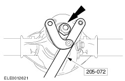
Drive Pinion and Drive Pinion Flange
Check the drive pinion flange runout when all other checks have failed to show the cause of vibration.
One cause of excessive drive pinion flange runout is incorrect installation of the axle drive pinion oil seal. Check to see if the spring on the oil seal lip has been dislodged before installing a new ring gear and drive pinion.
Axle Noise
NOTE:Before disassembling the axle to diagnose and correct gear noise, eliminate the tires, exhaust system, trim items, roof racks, axle shafts and wheel bearings as possible causes. Follow the diagnostic procedures.
REFER to: Noise, Vibration and Harshness (NVH) (100-04 Noise, Vibration and Harshness, Diagnosis and Testing).
The noises described as follows usually have specific causes that can be diagnosed by observation as the unit is disassembled. The initial clues are the type of noise heard during the road test.
Gear Howl and Whine
Howling or whining of the ring gear and drive pinion is due to an incorrect gear pattern, gear damage or incorrect bearing preload.
Bearing Whine
Bearing whine is a high - pitched sound similar to a whistle. It is usually caused by worn or damaged drive pinion bearings, which are operating at driveshaft speed. Bearing noise occurs at all driving speeds. This distinguishes it from gear whine which usually comes and goes as speed changes.
As noted, drive pinion bearings make a high - pitched, whistling noise, usually at all speeds. If however there is only one drive pinion bearing that is worn or damaged, the noise may vary in different driving phases. New drive pinion bearings must not be installed unless scoring or damage is found or there is a specific drive pinion bearing noise. A worn or damaged bearing will normally be obvious at disassembly. Examine the large diameter of the rollers for wear. If the drive pinion bearings original blend radius has worn to a sharp edge, a new front and rear drive pinion bearing must be installed.
NOTE:A low - pitched rumble normally associated with a worn or damaged wheel bearing can be caused by an exterior luggage rack or tires.
A wheel bearing noise can be mistaken for a drive pinion bearing noise. Check the wheel bearing for a spalled cup, and spalled or damaged rollers. Install a new wheel bearing if any of these concerns are detected.
Chuckle
Chuckle that occurs on coasting is usually caused by excessive clearance between the differential gear wheel hub and the differential case bore.
Damage to a gear tooth on the coast side can cause a noise identical to a chuckle. A very small tooth nick or ridge on the edge of a tooth can cause the noise.
Clean the gear tooth nick or ridge with a small grinding wheel. If the damaged area is larger than 3.2 mm, install a new gearset.
To check the ring gear and drive pinion, remove as much oil as possible from the gears with clean solvent. Wipe the gears dry or blow them dry with compressed air. Look for scored or damaged teeth. Also look for cracks or other damage.
If either gear is scored or damaged badly, a new ring gear and drive pinion must be installed.
- Lower the vehicle so that one rear wheel is resting on a wheel chock to prevent it from turning. The other rear wheel will be used to measure total rear axle backlash.
- Rotate the free wheel slowly, by hand, until the feeling of driving the rear axle is encountered. Place a mark on the side of the tire, 305 mm from the center of the wheel, with a crayon or chalk.
- While holding the crayon or chalk against the tire, rotate the wheel slowly in the opposite direction until the feeling of driving the rear axle is encountered again.
- Measure the length of the mark on the tire.
- If the length of the mark is 25 mm or less, the rear axle backlash is within specification.
- If the mark is greater than 25 mm, check for these conditions:
3. Excessive ring gear and drive pinion backlash. Follow the procedure for the type of rear axle to check backlash.
Axle Shaft Bearing Noise
Axle shaft bearing noise is similar to gear noise and differential drive pinion bearing whine. Axle shaft bearing noise will usually distinguish itself from gear noise by occuring in all driving modes (drive, coast, and float), and will persist with the transmission in NEUTRAL while the vehicle is moving at the speed in which the concern is occuring. If the vehicle makes this noise, remove the suspect axle shaft and install a new bearing and axle oil seal. Re - evaluate the vehicle for noise before removing any internal components.
Bearing Rumble
Bearing rumble sounds like marbles being tumbled. This condition is usually caused by a worn or damaged wheel bearing. The lower pitch is because the wheel bearing turns at only about one - third of the driveshaft speed. Wheel bearing noise also may be high - pitched, similar to gear noise, but will be evident in all driving modes.
Analysis of Inoperative Conditions
If the axle does not operate, it may be caused by broken welds or wheel bearing wear or damage.
Broken Welds
If axle housing welds are completely broken, install a new axle housing.
Wheel Bearing Wear or Damage
Because of the severe loads they must handle, new wheel bearings may be required at high mileage. If a wheel bearing fails at low mileage, it is often caused by overloading.
Symptom Chart
Symptom Chart
Driveline vibration exhibits a higher frequency and lower amplitude than does high - speed shake. Driveline vibration is directly related to the speed of the vehicle and is usually noticed at various speed ranges. Driveline vibration can be perceived as a tremor in the floor pan or is heard as a rumble, hum or boom. Driveline vibration can exist in all drive modes, but may exhibit different symptoms depending upon whether the vehicle is accelerating, decelerating, floating, or coasting. Check the driveline angles if the vibration is particulary noticeable during acceleration or deceleration, especially at lower speeds. Driveline vibration can be duplicated by supporting the axle upon a vehicle lift or upon axle stands, though the brakes may need to be applied lightly in order to simulate road resistance.
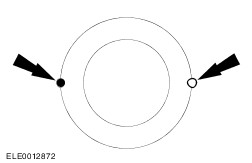
If the drive pinion flange runout exceeds 0.25 mm, remove the drive pinion flange, reindex the drive pinion flange one - half turn on the drive pinion and install it. REFER to: (205-02A Rear Drive Axle/Differential)
Drive Pinion Flange and Drive Pinion Seal - VIN Plate Axle Code: A/B/C/D/G/M/P/X/Y (In-vehicle Repair),
Drive Pinion Flange and Drive Pinion Seal (In-vehicle Repair).
- Check the runout again. If necessary, rotate the drive pinion flange until an acceptable runout is obtained. If the drive pinion flange runout is still more than 0.25 mm, install a new drive pinion flange.
- If excessive runout is still evident after installation of a new drive pinion flange, install a new ring gear set. Repeat the above checks until the runout is within specifications.
- Install the driveshaft.
REFER to: Driveshaft (205-01 Driveshaft, Removal and Installation).
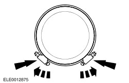
Tooth Contact Pattern Check - Gearset
- To check the gear tooth contact, paint the gear teeth with the special marking compound. A mixture that is too wet will run and smear; a mixture that is too dry cannot be pressed out from between the teeth.
- Use a box wrench on the ring gear bolts as a lever to rotate the ring gear several complete revolutions in both directions or until a clear tooth contact pattern is obtained.
- Certain types of gear tooth contact patterns on the ring gear indicate incorrect adjustment. Incorrect adjustment can be corrected by readjusting the ring gear or the drive pinion.
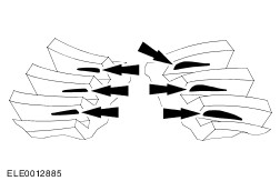
Contact Pattern Location
In general, acceptable ring gear tooth patterns must have the following characteristics:
- Drive pattern on the drive side ring gear well centered on the tooth.
- Coast pattern in the coast side ring gear well centered on the tooth.
- Clearance between the pattern and the top of the tooth.
- No hard lines where the pressure is high.
Acceptable ring gear tooth patterns for all axles.