| PINPOINT TEST B : THE PARKING BRAKE WILL NOT APPLY |
| TEST CONDITIONS | DETAILS/RESULTS/ACTIONS |
| B1: CHECK ADJUSTMENT OF THE REAR PARKING BRAKE CABLE |
| | 1 Operate the parking brake control several times to adjust the cable. |
| | Does the parking brake now engage correctly? Yes Parking brake is OK. TEST the system for normal operation. No |
| B2: CHECK THE BRAKE SHOES AND BRAKE DRUMS |
| | 1 Check the brake shoes and drums for grease or fluid on the linings and excessive wear. |
| | Are any concerns present? Yes CLEAN or INSTALL new brake shoes or brake drums as necessary. REFER to Section 206-02 Drum Brake. No |
| B3: CHECK FOR DAMAGED PARKING BRAKE CABLE(S) |
| | 1 Inspect the parking brake cable(s) for damage, rust or fraying. |
| | Are the parking brake cable(s) OK? Yes No REPAIR or INSTALL parking brake cable(s) as necessary. TEST the system for normal operation. |
| B4: CHECK OPERATION OF THE PARKING BRAKE ASSIST |
NOTE:The vehicle must be moved up to a maximum of two meters before the parking brake assist system operates. |
| | 1 Apply the park brake control until the first audible click is heard. |
| | 2 Move the vehicle in either direction with the parking brake control still applied until the parking brake assist activates. |
| | Does the parking brake assist operate? Yes TEST the system for normal operation. No |
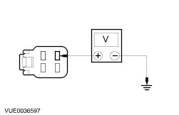
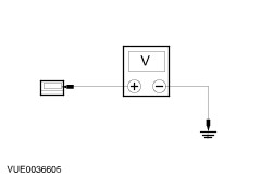
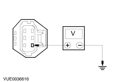
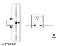
| B5: CHECK THE PARKING BRAKE MODULE FOR VOLTAGE |
| | 1 Ignition switch in position 0. |
| | 2 Disconnect Parking Brake Module C7051b. |
| | 3 Measure the voltage between the parking brake module C7051b pin 1, circuit 29-XL1 (OG/BU), harness side and ground. |
| | Is the voltage greater than 10 volts? Yes No |
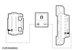
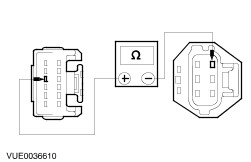
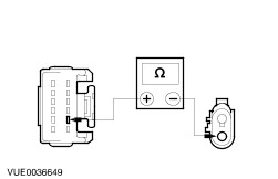
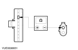
| B6: CHECK CIRCUIT 29-XL1 (OG/BU) FOR OPEN |
| | 1 Disconnect SVO fusebox C7052. |
| | 2 Measure the resistance between the parking brake module C7051b pin 1, circuit 29-XL1 (OG/BU), harness side and SVO fusebox C7052 pin 1, circuit 29-DG8 (OG/BU), harness side. |
| | Is the resistance less than 5 ohms? Yes No REPAIR the circuit. TEST the system for normal operation. |
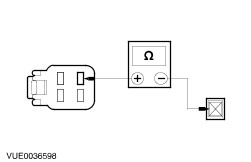
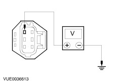
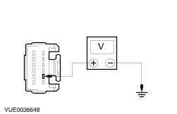
| B7: CHECK THE PARKING BRAKE MODULE FOR SWITCHED VOLTAGE |
| | 1 Disconnect Parking Brake Module C7051a. |
| | 2 Ignition switch in position II. |
| | 3 Measure the voltage between the parking brake module C7051a pin 5, circuit 14-XL2 (VT/BU), harness side and ground. |
| | Is the voltage greater than 10 volts? Yes No |
| B8: CHECK CIRCUIT 14-XL2 (VT/BU) FOR OPEN |
| | 1 Disconnect In-Line Fuse Holder C7055. |
| | 2 Measure the resistance between the parking brake module C7051a pin 5, circuit 14-XL2 (VT/BU), harness side and In-Line fuse holder C7055, circuit 15-FA5E (GN/BU), harness side. |
| | Is the resistance less than 5 ohms? Yes No REPAIR the circuit. TEST the system for normal operation. |
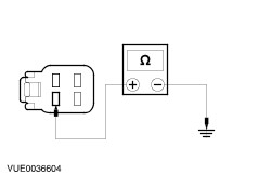
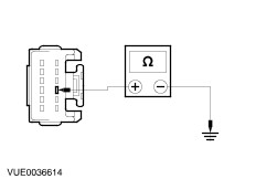
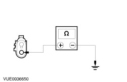
| B9: CHECK THE PARKING BRAKE MODULE FOR GROUND |
| | 1 Connect Parking Brake Module C7051a. |
| | 2 Disconnect Parking Brake Module C7051b. |
| | 3 Measure the resistance between the parking brake module C7051b pin 4, circuit 31-XL1 (BK), harness side and ground. |
| | Is the resistance less than 5 ohms? Yes No REPAIR circuit 31-XL1 (BK). TEST the system for normal operation. |
| B10: CHECK PARK BRAKE SWITCH |
| | 1 Disconnect Park Brake Switch C4066. |
| | 2 Ignition switch in position II. |
| | 3 Measure the voltage between the park brake switch C4066 pin 1, circuit 31S-GE44 (BK-RD), component side and ground. |
| | Is the voltage greater than 10 volts? Yes No INSTALL a new park brake switch. TEST the system for normal operation. |
| B11: CHECK CIRCUIT 31S-GE44 (BK/RD) FOR OPEN |
| | 1 Disconnect Parking Brake Module C7051a. |
| | 2 Measure the resistance between the parking brake module C7051a pin 3, circuit 31S-GE44C (BK/RD), harness side and the park brake switch C4066 pin 1, circuit 31S-GE44 (BK/RD), harness side. |
| | Is the resistance less than 5 ohms? Yes No REPAIR the circuit. TEST the system for normal operation. |
| B12: CHECK THE PARKING BRAKE WHEEL SPEED SENSOR USING WDS OSCILLOSCOPE |
| | 1 Connect Parking Brake Module C7051a. |
| | 2 Disconnect Parking Brake Wheel Speed Sensor C7057. |
| | 3 Using WDS oscilloscope, measure the parking brake wheel speed sensor input signal frequency between the speed sensor connector pin 1 and pin 2, while rotating the front right-hand wheel. |
| | Is the frequency pattern within working parameters? Yes No CHECK the wheel knuckle wheel speed sensor mounting is clean and free from foreign material. If the concern persists, INSTALL a new parking brake wheel speed sensor. REFER to Parking Brake Wheel Speed Sensor - in this section. TEST the system for normal operation. |
| B13: CHECK CIRCUIT 8-XL6 (WH/BU) FOR OPEN |
| | 1 Disconnect Parking Brake Module C7051a. |
| | 2 Measure the resistance between the parking brake wheel speed sensor C7057 pin 1, circuit 8-XL6 (WH/BU), harness side and the parking brake module C7051a, pin 8, circuit 8-XL6 (WH/BU), harness side. |
| | Is the resistance less than 5 ohms? Yes No REPAIR the circuit. TEST the system for normal operation. |
| B14: CHECK CIRCUIT 10-XL6 (GY/VT) FOR OPEN |
| | 1 Measure the resistance between the parking brake wheel speed sensor C7057 pin 2, circuit 10-XL6 (GY/VT), harness side and the parking brake module C7051a, pin 11, circuit 10-XL6 (GY/VT), harness side. |
| | Is the resistance less than 5 ohms? Yes No REPAIR the circuit. TEST the system for normal operation. |
| B15: CHECK CIRCUIT 29S-XL2 (OG/BU) FOR OPEN |
| | 1 Disconnect Parking Brake Actuator C7058. |
| | 2 Disconnect Parking Brake Module C7051b. |
| | 3 Measure the resistance between the parking brake actuator C7058 pin 1, circuit 29S-XL2 (OG/BU), harness side and the parking brake module C7051b pin 3, circuit 29S-XL2 (OG/BU), harness side. |
| | Is the resistance less than 5 ohms? Yes No REPAIR the circuit. TEST the system for normal operation. |
| B16: CHECK CIRCUIT 7-XL4 (YE/RD) FOR OPEN |
| | 1 Measure the resistance between the parking brake actuator C7058 pin 3, circuit 7-XL4 (YE/RD), harness side and the parking brake module C7051a pin 10, circuit 7-XL4 (YE/RD), harness side. |
| | Is the resistance less than 5 ohms? Yes No REPAIR the circuit. TEST the system for normal operation. |
| B17: CHECK CIRCUIT 8-XL4 (WH/RD) FOR OPEN |
| | 1 Measure the resistance between the parking brake actuator C7058 pin 4, circuit 8-XL4 (WH/RD), harness side and the parking brake module C7051a pin 4, circuit 8-XL4 (WH/RD), harness side. |
| | Is the resistance less than 5 ohms? Yes No REPAIR the circuit. TEST the system for normal operation. |
| B18: CHECK CIRCUIT 9-XL4 (BN/RD) FOR OPEN |
| | 1 Measure the resistance between the parking brake actuator C7058 pin 5, circuit 9-XL4 (BN/RD), harness side and the parking brake module C7051a pin 12, circuit 9-XL4 (BN/RD), harness side. |
| | Is the resistance less than 5 ohms? Yes No REPAIR the circuit. TEST the system for normal operation. |
| B19: CHECK FOR SUPPLY VOLTAGE TO THE PARKING BRAKE ACTUATOR |
| | 1 Connect Parking Brake Module C7051b. |
| | 2 Measure the voltage by backprobing between the parking brake actuator C7058 pin 6, circuit 31S-XL2 (BK/BU), harness side and ground. |
| | Is any voltage present? Yes No INSTALL a new parking brake actuator. REFER to Parking Brake Actuator - in this section. TEST the system for normal operation. If the concern persists, INSTALL a new parking brake module. REFER to Parking Brake Module - in this section. TEST the system for normal operation. |
| B20: CHECK FOR SHORT TO BATTERY POSITIVE VOLTAGE |
| | 1 Disconnect Parking Brake Module C7051b. |
| | 2 Measure the voltage between the parking brake actuator C7058 pin 6, circuit 31S-XL2 (BK/BU), harness side and ground. |
| | Is any voltage present? Yes REPAIR the short to battery positive. TEST the system for normal operation. No INSTALL a new parking brake module. REFER to Parking Brake Module - in this section. TEST the system for normal operation. |