| Removal and Installation General Equipment Worldwide Diagnostic System (WDS) Removal WARNING:Refer to: Supplemental Restraint System (SRS) Health and Safety Precautions (100-00 General Information, Description and Operation). | | -
Remove the steering wheel. Refer to: Steering Wheel (211-04 Steering Column, Removal and Installation). | | | -
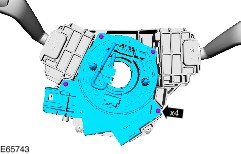
CAUTION:Take extra care not to damage the clips. | Installation WARNING:Refer to: Supplemental Restraint System (SRS) Health and Safety Precautions (100-00 General Information, Description and Operation). | | -
CAUTION:Take extra care not to damage the clips. -
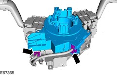
Align the steering wheel rotation sensor locating tangs to the clockspring. -
Make sure that the steering wheel rotation sensor retaining clips lock into position on the the clockspring. | | | -
NOTE:Make sure that the road wheels are in the straight ahead position. NOTE:Make sure that the turn signal lamp switch is in the off position. | | | -
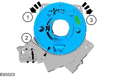
WARNING:If there is a break between installing the clockspring and steering wheel rotation sensor assembly and installing the steering wheel, the centralizing of the clockspring must be repeated. WARNING:If the centralization of the clockspring is in doubt, the centralizing of the clockspring must be repeated. CAUTION:The clockspring and steering wheel rotation sensor assembly must not be rotated in a clockwise direction more than 3 revolutions. -
Turn the clockspring rotor in a counterclockwise direction until a resistance is felt. -
Turn the clockspring rotor in a clockwise direction, until the arrow marked on the clockspring rotor aligns with the raised 'V' section on the clockspring body at approximately the 195 degrees position. -
Turn the clockspring rotor in a clockwise direction three turns. | | | -
CAUTION:Make sure that the clockspring rotor does not rotate. | | | -
Install the steering wheel. Refer to: Steering Wheel (211-04 Steering Column, Removal and Installation). | | | -
Configure the electronic stability assist program. | | |