
Sprinter 2500 V6-3.0L DSL Turbo (2008)
Pin Circuit
Description
1
4166 14BK/GY
RIGHT HEATED SEAT DRIVER
Pin Circuit
Description
1
551 14BK/VT
RIGHT HEATED SEAT DRIVER
2
552 14BK/GY
LEFT HEATED SEAT DRIVER
2
4167 14BK/VT
LEFT HEATED SEAT DRIVER
3
-
-
4
553 12RD/DG
FUSED B(+)
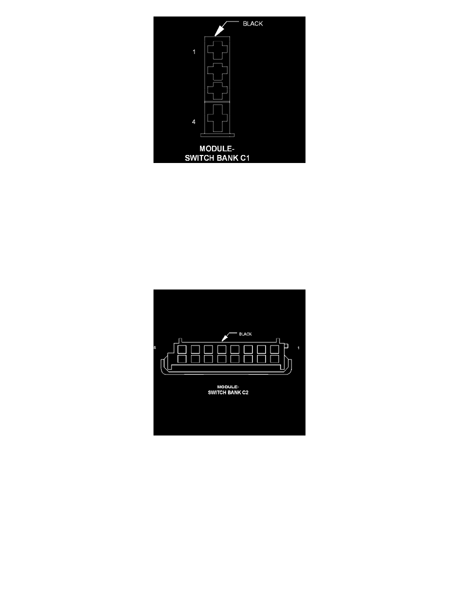
Connector:
Name :
MODULE-SWITCH BANK C2
Color :
BLACK
# of pins :
8
Pin Circuit
Description
1
548 18BR
GROUND
2
U758 18RD/YL
FUSED B(+)
3
549 20BR
CAN B BUS (-)
4
550 20BR/RD
CAN B BUS (+)
5
-
-
6
-
-
7
-
-
8
-
-