
Sprinter 2500 V6-3.0L DSL Turbo (2008)
Body Control Module: Service and Repair
Body Control Module - Installation
INSTALLATION
WARNING: To avoid serious or fatal injury on vehicles equipped with airbags, disable the supplemental restraint system before attempting
any steering wheel, steering column, airbag, seat belt tensioner, impact sensor, or instrument panel component diagnosis or service. Disconnect
and isolate the battery negative (ground) cable, then wait two minutes for the system capacitor to discharge before performing further
diagnosis or service. This is the only sure way to disable the supplemental restraint system. Failure to take the proper precautions could result
in accidental airbag deployment.
NOTE: Several versions of the Body Control Module (BCM) (also known as the Signal Acquisition and Actuation Module/SAM) are available,
which vary depending upon the standard and optional vehicle equipment. The size of the BCM housing changes with each version, which
should aid in identification. Be certain that a new BCM is the correct replacement for one that has been removed.
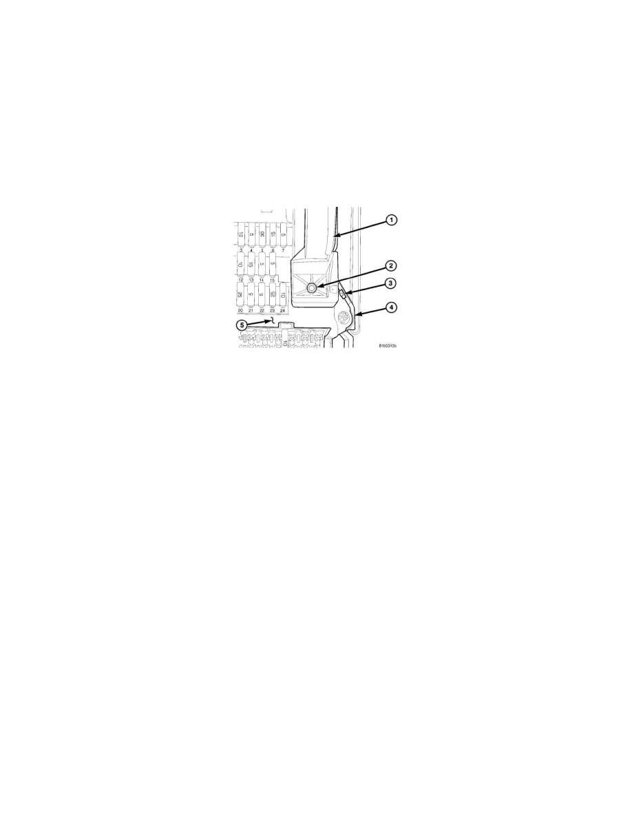
1. Position the Body Control Module (BCM) (1) (also known as the Signal Acquisition and Actuation Module/SAM) to the fuse and relay block (5)
(also known as the SRB).
2. Engage the horizontal nailhead pin on each side of the interface connector at the top of the BCM into the half-round cradle formations on each side
at the top of the fuse and relay box interface connector receptacle.
3. Rotate the lower end of the BCM downward until the interface connector halves are fully engaged.
4. Install and tighten the screw (2) that secures the lower mount of the BCM to the fuse and relay block. Tighten the screw securely.
5. Reinstall the fuse and relay block and the BCM to the vehicle as a unit. To reinstall the unit:
a. Insert the two posts integral to the upper edge of the fuse and relay block into the holes in the upper end of the mounting bracket (4) behind the
instrument panel.
b. Align the lower end of the fuse and relay block with the two alignment posts integral to the lower end of the mounting bracket on the dash
panel.
c. Push the lower end of the fuse and relay block forward over the alignment posts of the lower mounting bracket until the latch tab (3) on each
side snaps back into place.
6. Reconnect the external wire harness connections to the BCM.
7. Reinstall the trim onto the left cowl side inner panel. .
8. Reconnect the battery negative cable.