
Sprinter 2500 V6-3.0L DSL Turbo (2008)
Body Control Module: Description and Operation
Roof Control Module
Description
DESCRIPTION
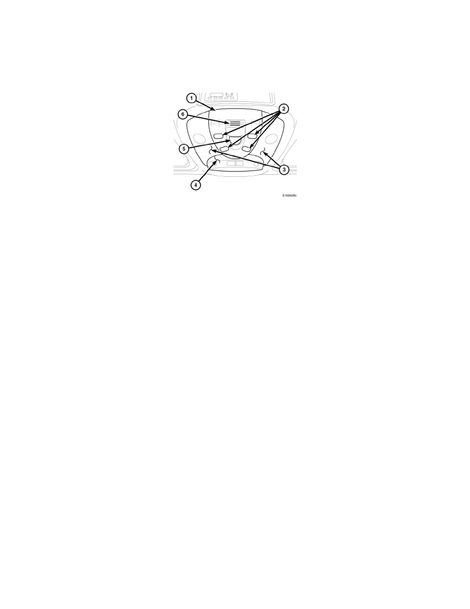
The Roof Control Module (RCM) (also known as the Overhead Control Panel/OCP control unit or DBE) is integral to the optional OCP (1) located on
the headliner between the front driver and passenger seats just behind the upper windshield opening header. The OCP is available in multiple
configurations, which vary from vehicle to vehicle depending upon the optional equipment in the vehicle. Besides the RCM, the OCP may include the
following features:
-
Automatic Interior Lighting and Reading Lamp Switches (2)
-
Eyeglasses Storage Compartment or optional Vehicle Theft Security System (VTSS) Front Interior Motion Sensor and Inclination Sensor
(4) - motion/inclination sensor includes Interior Protection OFF and Tow-Away Protection OFF Switches.
-
Front Dome and Reading Lamp Lenses (3)
-
Hands-Free Microphone for Telephone (6)
-
Power Sliding Sunroof Switch (5)
The RCM and OCP housings, the lamp lenses and the push buttons are constructed of molded plastic. Each push button has a smooth finish and is clearly
identified with the appropriate text or International Control and Display Symbol icons. Several of the push buttons feature Light Emitting Diode (LED)
units to provide panel lamps dimmer controlled back lighting for visibility at night, but these LED units are integral to the circuit board within the RCM
and are not serviceable.
Eight screws secure the RCM to the back of the OCP housing, while the OCP is secured above the headliner by two engagement tabs and two spring
clips. The back of the RCM housing has an integral connector receptacle containing terminal pins that connect the unit to the vehicle electrical system
through a dedicated take out and connector of the vehicle wire harness.
The individual switches in the RCM cannot be repaired and are not serviced individually. The incandescent bulbs for the dome and reading lamps are
available for individual service replacement. If any other component within the RCM is ineffective or damaged, the RCM unit must be replaced.
Operation
OPERATION
For information covering details of operation for the individual switches, sensors and circuits contained within or connected to the Roof Control Module
(RCM) (also known as the Overhead Control Panel/OCP control unit or DBE) or to the OCP, refer to the specific service information covering the
system or circuit to which that switch or sensor belongs.
The microprocessor-based RCM utilizes integrated circuitry to monitor hard wired analog and multiplexed inputs from its integral push button switches,
the optional power sliding sunroof switch, the optional rain/light sensor, the optional mobile telephone and the optional Vehicle Theft Security System
(VTSS) front interior motion sensor. In response to those inputs, the internal circuitry and programming of the RCM allow it to transmit electronic
message outputs to other electronic modules in the vehicle over the Controller Area Network (CAN) data bus. .
The RCM is connected to a fused B(+) circuit and receives a path to ground at all times. These connections allow it to remain functional regardless of the
ignition switch position. Any input to the RCM that controls a vehicle system function that does not require that the ignition switch be in the ON
position, prompts the RCM to wake up and transmit on the CAN data bus.
The hard wired circuits between components related to the RCM may be diagnosed using conventional diagnostic tools and procedures. Refer to the
appropriate wiring information. The wiring information includes wiring diagrams, proper wire and connector repair procedures, details of wire harness