
K 2500 Truck 4WD V8-379 6.2L DSL VIN C FI (1989)
Technical Service Bulletin # 905104
Date: 901001
Brake Rotors - Inspection Information
GMC NUMBER:
90-5-104
GROUP:
5 Brakes
DATE:
October, 1990
CORPORATE
NUMBER:
065009
SUBJECT:
BRAKE ROTORS: INFORMATION, REFINISHING, LATERAL RUNOUT, PARALLELISM, CALIPER INSPECTION AND
BURNISHING
MODELS:
1988-90 C/K TRUCKS
In the manufacturing of brake rotors, all the tolerances regarding surface finish, parallelism and lateral runout are held very closely. The maintenance of
these tolerances provide the surface necessary to prevent a loss of braking performance. C1, C2, and C3 trucks have a one piece rotor and hub assembly
with loose outer and inner bearings. C1 trucks under 5600 G V W R have a 1" rotor. C1 trucks over 5600 G V W R, C2 and C3 trucks all have 1-1/4"
rotors. The rotor on the K2 and K3 with C6P brakes is a complete three-piece assembly consisting of a 1-1/4" rotor, bearings and hub. The rotor on C/K3
with R05 (dual rear wheels) is a complete four-piece assembly consisting of a rotor, bearings, hub, and extension. The rotor is 1-1/4" for 1988-1989
models, 1-1/2" for 1990 models. The C3 with R05 is a one piece casting but also has 1 1/4" wide rotors for 1988-1989 models and 1-1/2" wide rotors for
90 models. The rotors on the K1 and K2 models are composite construction and require special tool J 37620 when service is required. Light scoring of
the rotor surface not in excess of 0.38 mm (0.015-inch) in depth is normal, This condition will not affect brake operation.
Lateral Runout
Lateral runout is the movement of the rotor from side to side as it rotates on the spindle. This could also be referred to as "rotor wobble". This movement
causes the brake pad and piston to be knocked back into its bore. This condition results in additional pedal travel and a vibration during braking.
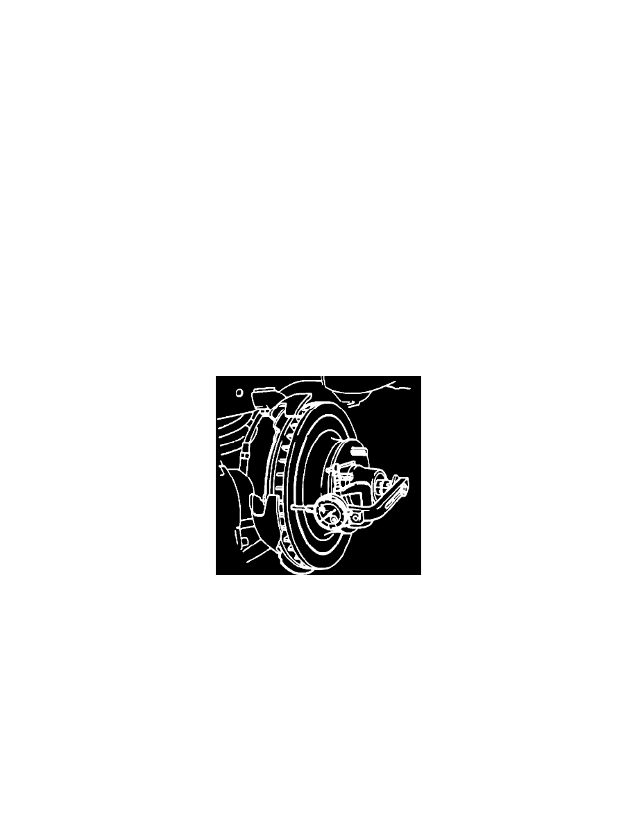
Figure 1 (2WD Model Pictured)
Inspecting for Lateral Runout (see Figure 1)
1.
Install tool J 37620 on K1, K2 trucks to provide clamp load to simulate "as installed" conditions.
2.
Adjust the wheel bearings to eliminate all freeplay (2 wheel drive only).
3.
Attach a dial indicator to some portion of the suspension.
^
The point of the stylus must contact the rotor face about 25 mm (1-inch) from the edge of the rotor.
4.
Turn the rotor one complete rotation.
^
The lateral runout should not exceed 0.13 mm (0.005-inch)
5.
Readjust the wheel bearings, refer to section 3C of the appropriate service manual (2 wheel drive only).
Parallelism