
K 2500 Truck 4WD V8-379 6.2L DSL VIN C FI (1989)
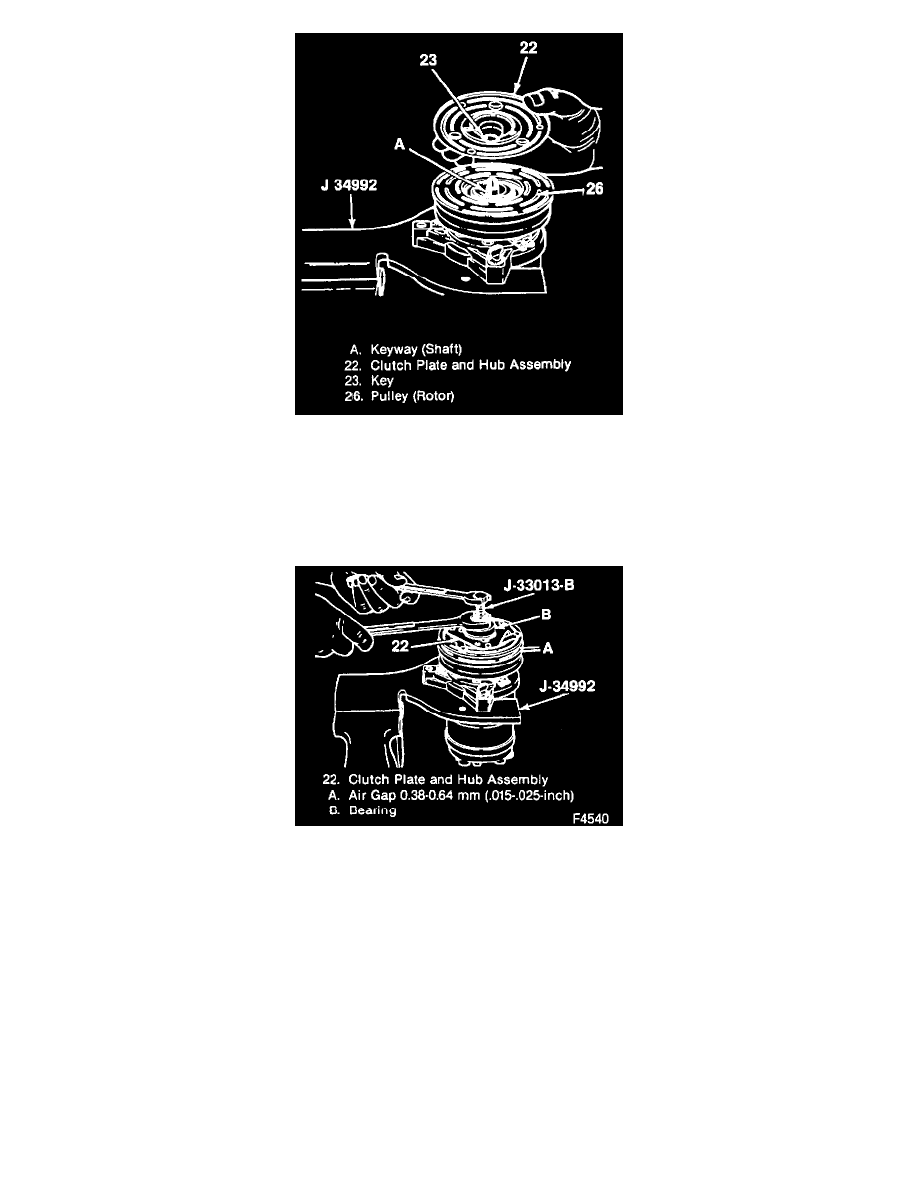
Removing The Clutch Plate And Hub & Shaft Key
^
Allow the shalt key (23) to extend 3.2 mm (1/8-inch) out of the bottom of the hub keyway.
^
The shaft key (23) is curved slightly to give an interference fit in the hub key groove.
Important
^
Do not drive or pound on the clutch hub or the shaft (20). Internal damage to the compressor may result.
Installing The Clutch Plate & Hub Assembly
2. Clutch plate and hub assembly (22).
^
Make sure the contact surfaces of the clutch plate (22) and the pulley (26) are clean.
^
Remove the forcing screw tip from J 33013-B and reverse the body direction on the center screw.
^
Install J 33013-B with bearing (B).
^
Back off J 33013-B body enough to allow the center screw to be threaded against the end of the compressor shaft.
^
Hold the center screw with a wrench and tighten the hex portion of J 33013-B body to press the hub onto the shaft (38). After tightening the
body several turns, remove J 33013-B and check that the shaft key (23) is properly in place in the keyway, then install the clutch plate and hub
assembly (22) to its final position.
^
Measure the air gap between contact surfaces of the clutch plate and hub assembly (22) and the pulley (26). The gap should be 0.38-0.64 mm
(0.015-0.025-inch).
^
Remove J 33013-B.
3. Shaft nut (21).
Inspect
^
Position of the shaft (even with or slightly above the clutch hub).
^
Use J 33027-A to hold the clutch plate and hub assembly (2).