
Suburban 3/4 Ton 4WD V8-305 5.0L (1986)
Pinion Gear: Service and Repair
Corporate and Eaton
9 1/2 Inch Ring Gear
PINION DEPTH ADJUSTMENT
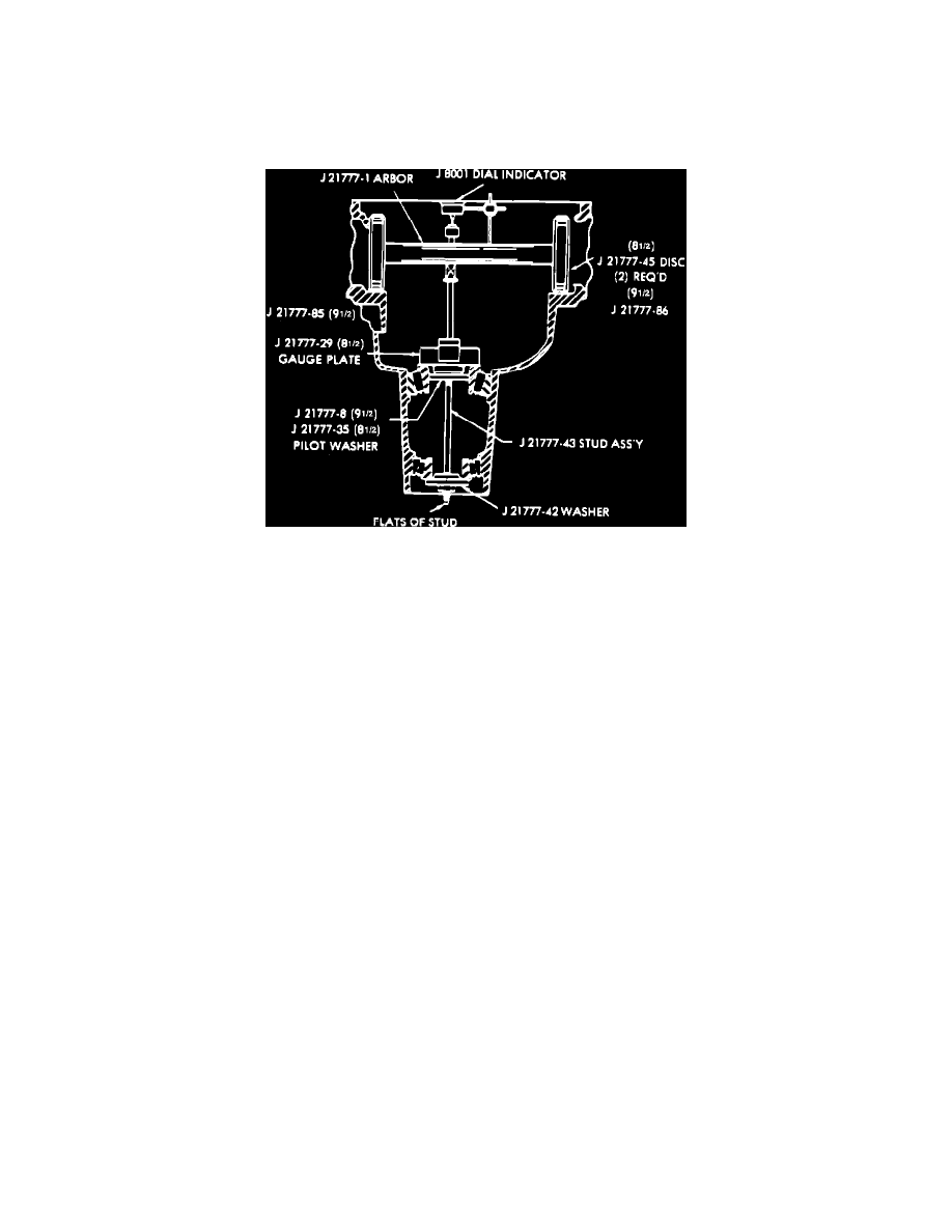
Fig. 9 Pinion Depth Gauge Installation
If original ring gear and pinion assembly and rear pinion bearing are to be reused, original depth adjusting shim can be used. However, if
ring gear and pinion or rear pinion bearing requires replacement, pinion depth must be adjusted using following procedures.
1.
Install pinion bearing races to be used in housing using suitable driver.
2.
Lubricate pinion bearings and install bearings in races.
3.
Mount depth gauging jig in housing noting the following.
Use gauge assembly tool No. J-21777-01, Fig. 9, or suitable equivalent. Follow all
tool manufacturer's recommendations when installing gauge assembly.
a.
Assemble gauge plate on preload stud.
b.
Hold pinion bearings in position, insert stud through rear bearing and pilot, then front bearing and pilot, install retaining nut and tighten nut
hand tight.
c.
Rotate tool to ensure that bearings are properly seated.
d.
Hold preload stud and tighten nut until 20 inch lbs.
torque is required to rotate stud. Tighten nut in small increments, checking rotating
torque after each adjustment using suitable torque wrench.
e.
Mount side bearing discs on arbor, using step that corresponds to base of housing.
f.
Mount arbor and plunger assembly in housing ensuring that side bearing discs are properly seated, install bearing caps and tighten cap bolts
to prevent bearing discs from moving.
4.
Mount suitable dial indicator on arbor stud with indicator contact button bearing against top of arbor plunger.
5.
Preload indicator 1/2 revolution, then secure to arbor stud in this position.
6.
Place arbor plunger on gauge plate, rotate plate as needed so that plunger rests directly on button corresponding to ring gear size.
7.
Slowly rock plunger rod back and forth across button while observing dial indicator.
8.
At point on button where indicator registers greatest deflection, zero dial indicator.
Perform steps 7 and 8 several times to ensure correct
setting.
9.
Once verified zero setting is obtained, swing plunger aside until it is clear of gauge plate button and record dial indicator reading.
Indicator will
now read required pinion depth shim thickness for ``nominal'' pinion.
10.
Inspect rear face of drive pinion to be installed for a pinion code number. This number indicates in thousandths of an inch necessary modification
of pinion shim thickness obtained in step 9.
11.
Select pinion depth adjusting shim as follows:
a.
If pinion is stamped with a plus (+) number, add that number of thousandths to dimension obtained in step 9.
b.
If pinion is stamped with a minus (-) number, subtract that many thousandths from dimension obtained in step 9.
c.
If pinion is not stamped with plus or minus number, dimension obtained in step 9 is correct shim thickness.
12.
Remove gauging tool and pinion bearings from housing.
DRIVE PINION INSTALLATION
1.
Install pinion bearing races in housing, if not previously installed, using suitable drivers to ensure that races are squarely seated.