
Suburban 3/4 Ton 4WD V8-305 5.0L (1986)
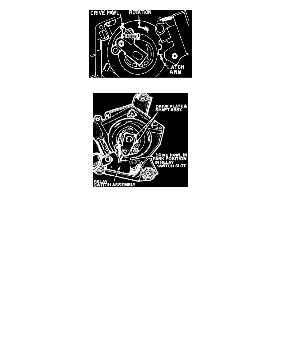
Fig. 6 Gearbox relay & drive gear assembly. Shown out of park position
Fig. 7 Gearbox relay & drive gear assembly. Shown in park position
STANDARD (NON-PULSE) WIPER OPERATION
When ignition is on, battery voltage is supplied to gearbox relay terminal 2, Fig. 3. When terminal 1 is grounded, relay contacts close and current is
supplied to the motor. Current flows through the series field to a splice where it is divided, and part passes through the armature to the motor housing
ground, and part through the shunt field. Motor speeds are determined by the amount of current flowing through the shunt field.
Placing wiper switch in low position grounds gearbox relay terminals 1 and 3. The relay contacts close, shunt field current flows directly to ground at
the switch through terminal 3, and the motor runs at low speed. Placing wiper switch in high grounds relay terminal 1, but terminal 3 remains open.
Shunt field current flows to ground through a 20 ohm resistor connected between terminals 1 and 3, and the motor runs at a higher speed due to the
weakened shunt field.
Placing wiper switch in off position opens the circuit to the gearbox relay magnet switch. This allows a spring loaded arm to move into the path of the
output gear drive pawl, Fig. 6, while relay contacts remain closed. The shunt field is grounded through the wiper switch and the motor operates at low
speed, allowing the gear mechanism to park the wipers and stop the motor.
As the output gear rotates, the drive pawl engages the latch arm on the gear box relay, and the output gear is unlocked from the drive pawl, lock pawl
and drive plate. Since the output shaft and gear shaft are off center, continuing rotation causes a cam action which moves the drive pawl into a slot in the
gearbox relay and allows wipers to move below their lowest point of normal travel. The drive pawl pushes the latch arm against the gearbox relay
contacts, opening the contacts and stopping the motor in park position, Fig. 7.
PULSE WIPER OPERATION
Modified Pulse System
Models equipped with pulse wipers use a motor similar to the one used on standard wiper systems which has been modified to provide a delay wipe
mode. In addition to standard wiper system components, the modified pulse system includes a voltage feed circuit to the wiper switch and a variable
resistor in the switch, a pulse relay and holding switch mounted on the washer pump, and a timer circuit. The timer circuit, consisting of a capacitor,
transistor and two diodes, is mounted in the washer pump or contained in a separate module.
The gearbox relay functions in a similar manner on both standard and pulse systems, but on pulse systems the gearbox relay supplies voltage to the
pulse relay which controls current flow to the motor windings. In all wiper switch positions except delay, the gearbox and pulse relays are grounded
simultaneously through the wiper switch, and the motor operates as outlined in ``Standard (Non-Pulse) Wiper Operation.'' When wiper switch is in delay
position, pulse relay operation is controlled by the timer circuit.
Placing wiper switch in delay position grounds gearbox relay terminals 1 (relay) and 3 (shunt field) at the switch, and battery voltage is supplied to the
timer circuit capacitor through the variable resistor in the switch. When the capacitor is fully charged, it activates the timer transistor. The transistor