
Yukon/Denali 2WD V8-6.0L VIN U (2004)
^
C222 (4 Cavities) (w/HP2) - Behind the left side I/P access panel
^
Refer to the Master Electrical Component List for additional location information.
1.
Remove the appropriate side door sill plate.
2.
Remove the appropriate side hinge pillar panel.
3.
Locate the IP harness to inflatable restraint module yellow 4-way connector C221 or C222.
4.
Inspect the IP harness to inflatable restraint module connector C221 or C222 for proper connection.
5.
Disconnect and reconnect the IP harness to inflatable restraint module connector C221 or C222 THREE times.
6.
Clear the DTC and road test the vehicle.
^
If DTCs B0013, B0014, B0017, B0018, B0024, B0026, B0043, B0044 DOES NOT reset, no additional repairs are necessary. Continue with
step 10.
^
If DTCs B0013, B0014, B0017, B0018, B0024, B0026, B0043, B0044 DOES reset, the most likely cause is high resistance in the IP harness
to inflatable restraint module connector C221 or C222. Continue with the next step.
7.
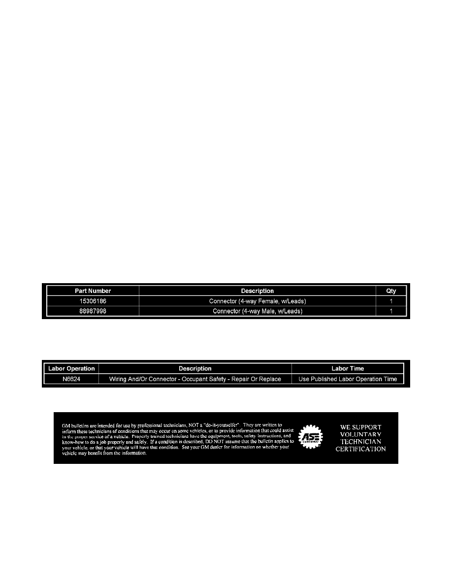
Replace the appropriate connector C221 and/or C222, P/N's 15306186 and 88987998. Refer to SIR/SRS Wiring Repairs (SI Document ID
#325229).
8.
Road test the vehicle and confirm that the repair is complete.
9.
Install the driver's side hinge pillar panel.
10.
Install the driver's side door sill plate.
Parts Information
Warranty Information
For vehicles repaired under warranty, use the table above.
Disclaimer