
Accord L4-2.4L (2005)
-
Loss of communicator DTCs. Begin troubleshooting with the lowest number first (Example: if DTC B1006 and B1058 are retrieved, begin by
troubleshooting B1006).
-
Signal error DTCs.
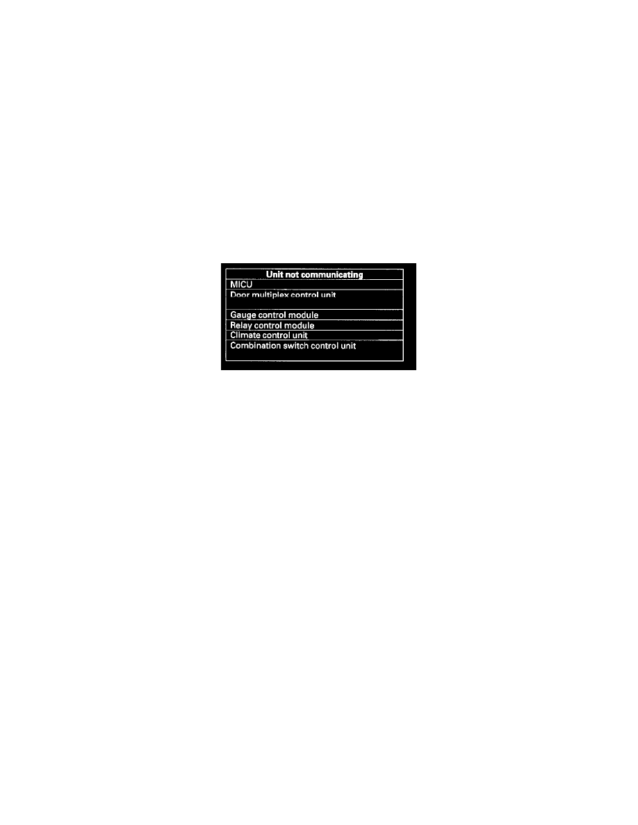
Troubleshooting - B-CAN System Diagnosis Test Mode B
Troubleshooting - B-CAN System Diagnosis Test Mode B
NOTE:
-
Perform this diagnosis if any of the control units are not communicating (Not Available displayed in the HDS.) as found by the B-CAN system
Diagnosis Test Mode A.
-
Always cycle the ignition switch within 3 seconds when prompted in the DTC troubleshooting procedures.
1. Using the Honda Diagnostic System (HDS), select the system that has the symptom from the BODY ELECTRICAL MENU.
2. Select DTCs, and then check for loss of communication DTCs (use the DTC Troubleshooting Index to find the DTC type).
Are loss of communication DTCs indicated?
YES - Go to step 3.
NO - Replace the MICU.
3. Perform the input test for the unit not communicating with the HDS.
Troubleshooting - B-CAN System Diagnosis Test Mode C
Troubleshooting - B-CAN System Diagnosis Test Mode C
NOTE:
-
Perform this diagnosis if a component that is controlled by the B-CAN system does not stop or does not turn off.
-
If the component does not turn ON, go to B-CAN System Diagnosis Test Mode D.
-
See the B-CAN system unit input/output index for a list of input and output devices and the control units that monitor the input and controls the
output devices.
-
Always cycle the ignition switch within 3 seconds when prompted in the DTC troubleshooting procedures.
1. Check for DTCs by selecting the TEST MODE MENU from the Honda Diagnostic System (HDS).
Are any DTCs indicated?
YES - Go to B-CAN System Diagnosis Test Mode A.
NO - Go to step 2.
2. Turn OFF the switch that controls the malfunctioning component.
3. Select DATA LIST from the TEST MODE MENU, and check the input of the switch that controls the component.
Does the tester indicate the switch is OFF?
YES - Go to step 4.
NO - Go to step 6.
4. In the DATA LIST of, check the output signal of the malfunctioning component.
Is the output signal OFF?
YES - Go to step 5.
NO - Replace the control unit that controls the device that will not turn OFF.