
Accord L4-2.4L (2005)
NO - Replace the component.
7. With the malfunctioning output device connected, connect a voltmeter between the malfunctioning output device and body ground on the wire that
the control unit uses to control the output device circuit.
8. Select MISC. TEST from the TEST MODE MENU, and do the forced operation test of the malfunctioning component.
Is there a change in voltage (12 V to 0 V or 0 V to 12 V)?
YES - Replace the component.
NO - Replace the control unit that controls the malfunctioning component.
9. Select DATA LIST from the TEST MODE MENU, and make sure the switch signal input for the malfunctioning system indicates a change when
operated.
Does the switch input indicated ON when the switch is ON?
YES - Replace the control unit that controls the malfunctioning component.
NO - Go to step 10.
10. Check the switch and its ground (if applicable), then check for an open or a short in the wire between the switch and the control unit that monitors
it.
Is the switch and the wire harness OK?
YES - Replace the control unit that monitors the switch.
NO - Replace the switch or repair the wire harness.
Troubleshooting - B-CAN System Diagnosis Test Mode 1 and Test Mode 2 (Without the HDS)
Troubleshooting - B-CAN System Diagnosis Test Mode 1 and 2 (Troubleshooting Without the HDS)
1. Check the No. 7 (10 A) fuse and No. 21 (7.5 A) fuse in the under-dash fuse/relay box.
Are the fuses OK?
YES - Go to step 2.
NO - Find and repair the cause of the blown fuse.
2. Remove the left kick panel.
3. Turn the ignition switch ON (II).
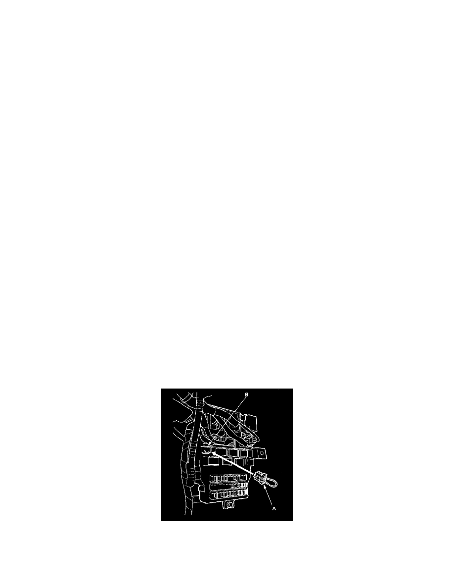
4. Connect the MFCS Service connector (A) to the MCIC socket (B) in the under-dash fuse/relay box.
5. Wait 5 seconds, then watch the ceiling light.
6. If there is a DTC, the ceiling light and ignition switch light will blink, pause, then repeat the DTC as long as the ignition switch ON (II).