
H1 V8-65L DSL Turbo (1999) Crankshaft Position Sensor Diagrams
Crankshaft Position Sensor: Description and Operation
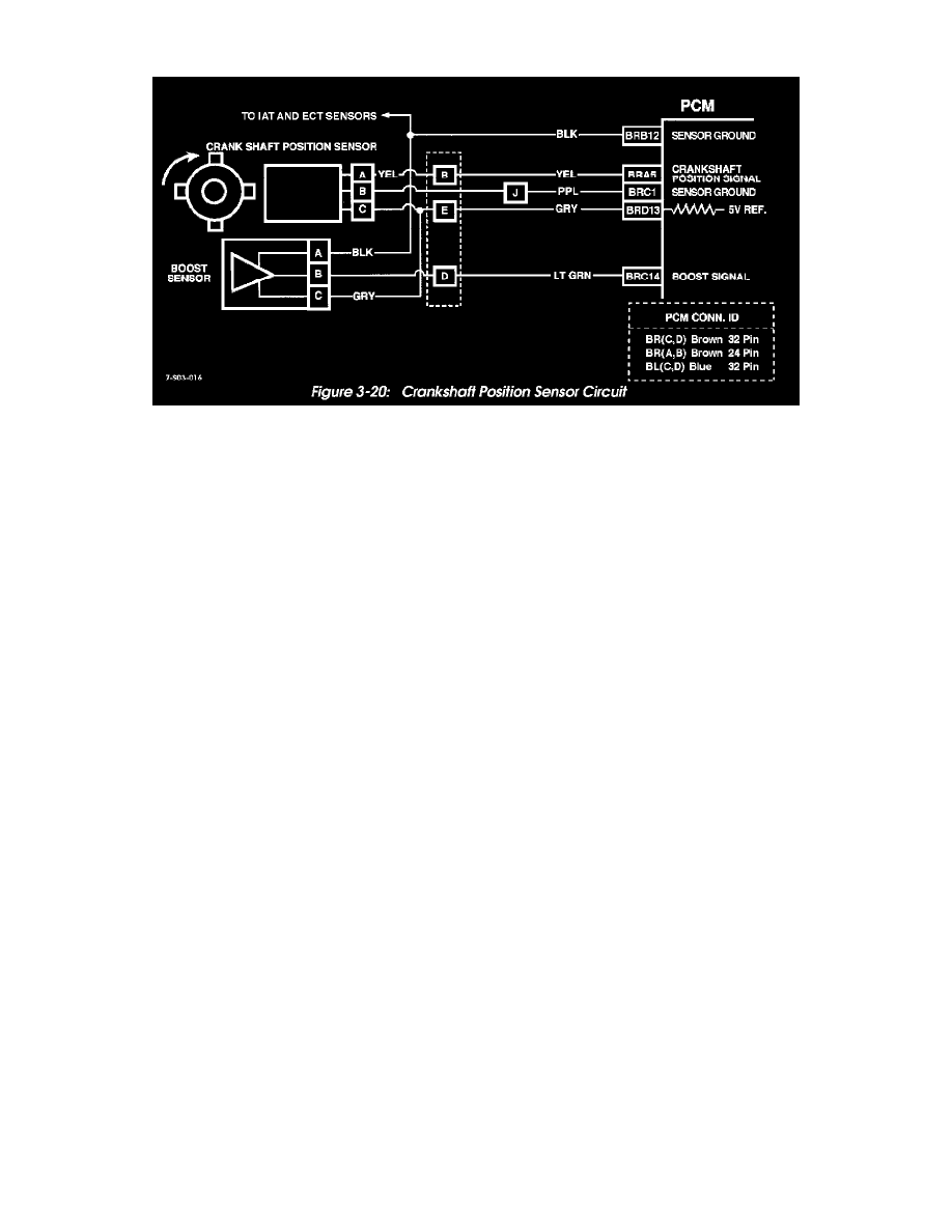
Figure 3-20: Crankshaft Position Sensor Circuit
Crankshaft Position Sensor
The crankshaft position sensor is a Hall-effect device that monitors crankshaft position and rpm. Four reference teeth 90° apart, on the crankshaft timing
sprocket cause the devise to turn "ON" or "OFF" producing a digital signal. This occurs as each tooth passes near the sensor magnetic field turning the
sensor "ON". The sensor transmits information to the PCM in the form of a 5 volt digital signal.
A sensor fault will cause a "crank reference missed" reading to occur. The scan tool will display the number of reference pulses missed. Normal reading
is zero.
If a sensor fault occurs, check the sensor wiring and connectors for shorts, opens, grounds, or loose connectors (Figure 3-20).
Sensor Test
1. Disconnect wires at fuel shut-off solenoid.
2. Connect voltmeter between PCM terminal BRA5 and ground and crank engine.
-
If meter indicates 5 volts, sensor is OK.
-
If meter indicates less than 5 volts or zero volts, check 5 volt reference at PCM terminal BRD13.
-
If 5 volt reference is OK, problem is bad connection or failed sensor.