
Hombre L4-2.2L CPC (1996)
2. Antenna location.
3. Transceiver wiring located too close to vehicle electronic modules or wiring.
4. Poor shielding or poor connectors on antenna feed line.
Check for 1990/1991 model year bulletin detailing Installation Guidelines For Aftermarket Accessories.
Probing (Frontprobe & Backprobe)
After probing, when reconnecting connectors or replacing terminals, always be sure to reinstall Connector Position Assurance (CPA) and Terminal
Position Assurance (TPA).
Frontprobe
When frontprobing of connectors is required, always use a mating terminal adapter from Connector Test Adapter Kit (J 35616-A). The use of
proper adapters will ensure that proper terminal contact integrity is maintained. (refer to Procedures in Checking Terminal Contact).
Backprobe
Only backprobe connector terminals when specifically called for in diagnostic procedures. Since backprobing can be a source of damage to
connector terminals, extra care must be taken to avoid deforming the terminal, either by forcing the test probe too far into the cavity or by using
too large a test probe.
After backprobing any connector, always check for terminal damage. If terminal damage is suspected, check for proper terminal contact, refer to
Checking Terminal Contact.
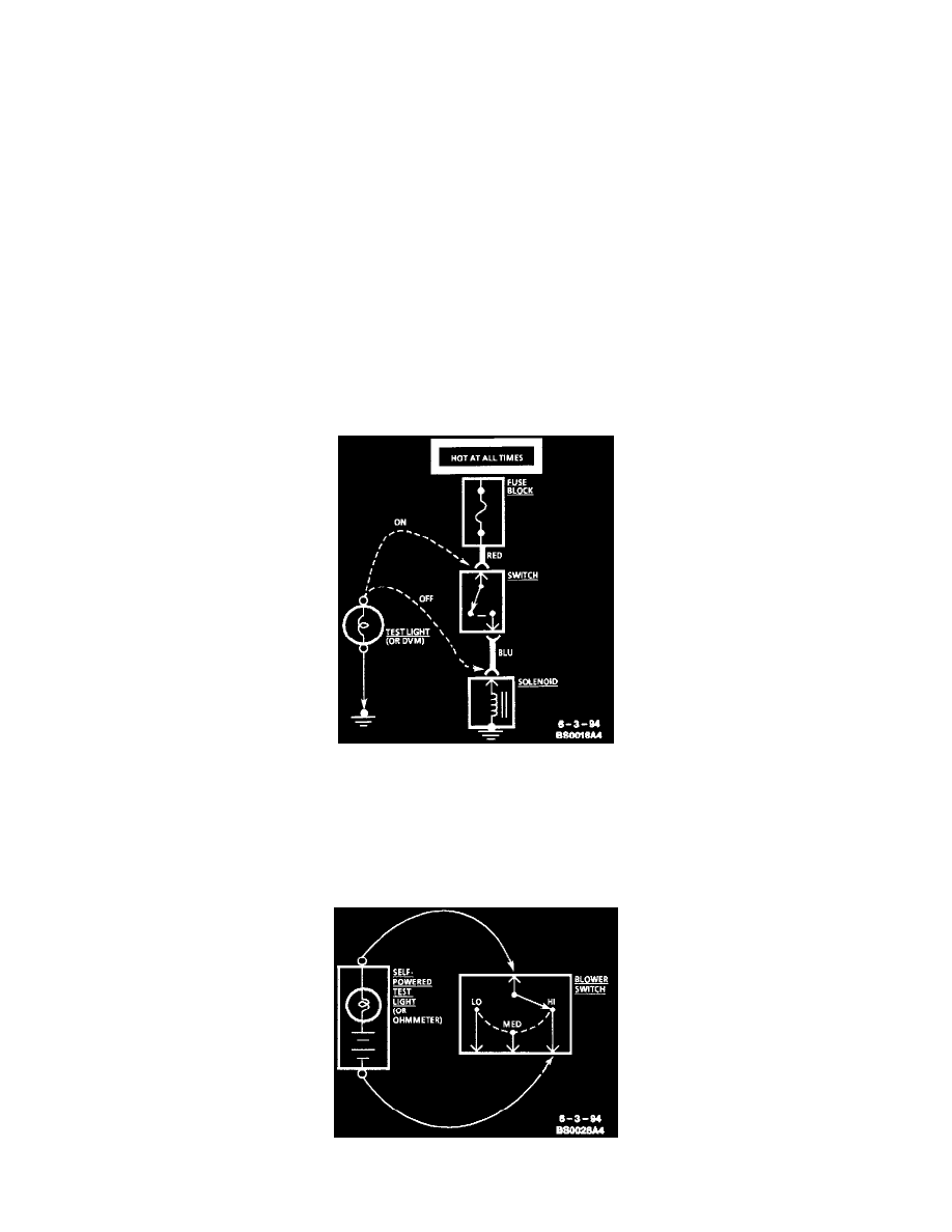
Testing For Voltage
Voltage Check
1. Connect one lead of a test light to a known good ground. When using a Digital Voltmeter (DVM), be sure the voltmeter's negative lead is
connected to ground.
2. Connect the other lead of the test light or voltmeter to a selected test point (connector or terminal).
3. If the test light illuminates, there is voltage present. When using a DVM, note the voltage reading.
Testing For Continuity
Continuity Check Through A Switch