
Hombre S Regular Cab 4WD V6-4.3L (1999)
Steps 15 - 18
Test Description
The numbers below refer to the step numbers on the diagnostic table.
1. This step determines if the scan tool may be powered up by the data link connector.
2. Most of the diagnostic procedures require a scan tool. Serial data must be available. This step verifies that communication may be established with
the BCM.
3. This step tests for any diagnostic trouble codes (DTCs) that are stored in the BCM. If the scan tool is able to read the DTCs, the serial data line is
OK.
4. This step tests for Class 2 communications with other systems. If the scan tool is able to read the data, the Class 2 serial data line is OK.
5. This step inspects the TBC fuse. The TBC fuse is located in the underhood fuse block.
6. This step determines if the underhood fuse block is supplying voltage to the TBC fuse.
7. This step determines if the BCM power CKT 1140 is open between the BCM and the TBC fuse.
8. This step determines if the BCM ground CKT 1850 is open.
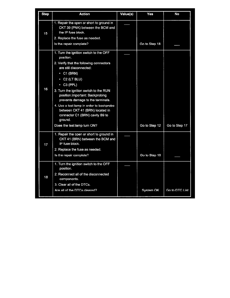
12. This step determines if the following components are good. The no-start condition indicates that the malfunction may relate to Passlock (TM) or
engine controls:
-
The BCM power and ground circuits
-
The BCM
14. This step determines if the BCM power CKT 39 is open between the BCM and the GAUGES fuse.