
Hombre S Regular Cab 4WD V6-4.3L (1999)
This test checks a short to ground along a wire or through a connection, or switch.
With a DMM Set to Ohmmeter Function
1. Remove the open fuse.
2. Disconnect the battery.
3. Disconnect the load.
4. Connect one lead of the DMM to the fuse terminal on the load side
5. Connect the other lead to a known good ground.
6. Beginning near the fuse block, wiggle the harness from side to side. Continue this at convenient points (about 6 inches apart) while watching the
DMM.
7. When the DMM displays low or no resistance, there is a short to ground in the wiring near that point.
With a DMM Set to Voltage Function
1. Remove the open fuse.
2. Disconnect the load.
3. Connect a DMM across the fuse terminals (be sure that the fuse is powered).
4. Beginning near the fuse block, wiggle the harness from side to side. Continue this at convenient points (about 6 inches apart) while watching the
DMM.
5. When the DMM displays voltage, there is a short to ground in the wiring near that point.
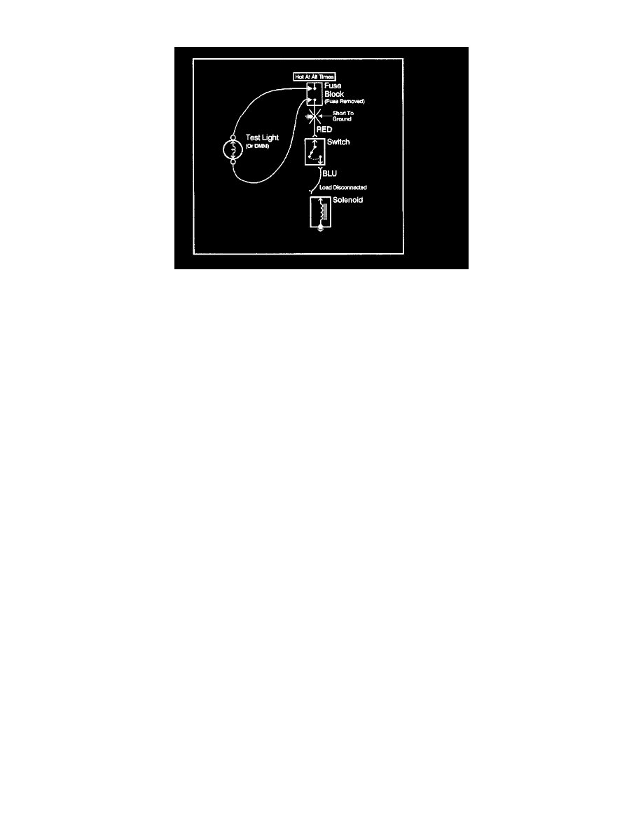
With a Test Light
1. Remove the open fuse.
2. Disconnect the load.
3. Connect a test light across the fuse terminals (be sure that the fuse is powered).
4. Beginning near the fuse block, wiggle the harness from side to side. Continue this at convenient points (about 6 inches apart) while watching the
test light.
5. When the test light glows there is a short to ground in the wiring near that point.
Fuse Powering Several Loads
1. Review the system schematic and locate the fuse that is open.
2. Open the first connector or switch leading from the fuse to each load.
3. Connect a DMM across the fuse terminals (be sure that the fuse is powered).
-
When the DMM displays voltage the short is in the wiring leading to the first connector or switch.
-
If the DMM does not display voltage refer to the next step.
4. Close each connector or switch until the DMM displays voltage in order to find which circuit has the short.
Troubleshooting With A Digital Multimeter
NOTE: Do not insert a DMM test probe into any connector or fuse block terminal The diameter of the DMM test probe will deform most terminals. A
deformed terminal can cause a poor connection between the device, which can result in system failures. Always use the J 35616-A Connect Test Adapter
Kit when using a DMM in order to probe terminals.
Important: Circuits which include any solid state control modules, such as the PCM, should be tested only with a 10 megohm or higher impedance J
39200 digital multimeter.
The J 39200 Instruction Manual is a good source of information and should be read thoroughly upon receipt of the DMM as well as kept on hand for