
Hombre S Regular Cab 4WD V6-4.3L (1999)
NOTE: Do not insert a DMM test probe into any connector or fuse block terminal The diameter of the DMM test probe will deform most terminals. A
deformed terminal can cause a poor connection between the device, which can result in system failures. Always use the J 35616-A Connect Test Adapter
Kit when using a DMM in order to probe terminals.
1. Remove the negative battery cable.
2. Place the leads of the DMM in COM (black) and V/ohms (red) inputs.
3. Set the rotary dial of the DMM to ohms.
4. Press the PEAK MIN MAX button.
5. Connect one lead of the DMM to one end of the circuit to test.
6. Connect the other lead to the other end of the circuit.
7. If the DMM displays low or no resistance and a tone is heard the circuit being tested has good continuity.
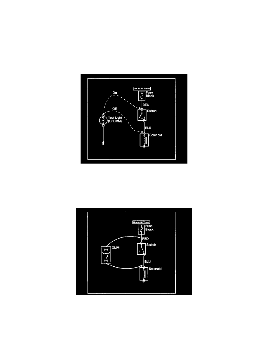
With a Test Light
This test checks for continuity along a wire, through a connection or switch.
NOTE: Do not insert a DMM test probe into any connector or fuse block terminal The diameter of the DMM test probe will deform most terminals. A
deformed terminal can cause a poor connection between the device, which can result in system failures. Always use the J 35616-A Connect Test Adapter
Kit when using a DMM in order to probe terminals.
1. Remove the fuse from the suspect circuit.
2. Connect one lead of the test light to one end of the circuit to test
3. Connect one end of the circuit to be tested to ground.
4. If the test light is not self-powered connect the other lead to a battery positive voltage source.
5. If the test light illuminates (full intensity) then the circuit being tested has good continuity.
Testing For Short to Ground