
Hombre S Regular Cab 4WD V6-4.3L (1999)
Repair and Verify Fix
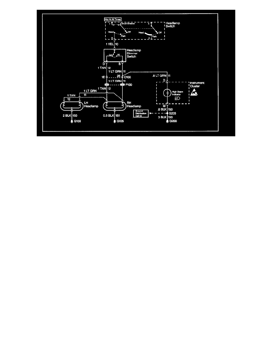
From isolating the root cause, basically the problem has been diagnosed. Using the Component Location
Table and the corresponding figure, quickly find C100 and the LT GRN wire, locate the exact trouble point and make the repair.
Check the thoroughness of the repair by performing a final system check on the headlamp circuit. This of course means making sure that both high
beams, both low beams, and the high beam indicator are working.
Testing For Electrical Intermittents
Use the following procedure to detect an intermittent circuit that is currently operating normally.
Important: The J 39200 must be used to perform the following procedure since the DMM can monitor current, resistance or voltage while recording
the minimum (MIN), and maximum (MAX) values measured.
1. Connect the J 39200 to both sides of a suspected connector, (still connected) or from one end of a suspected circuit to the other.
Important: Refer to Troubleshooting with a Digital Multimeter
2. Select the appropriate voltage mode on the DMM.
3. Press the Range button to select the desired voltage range.
4. Press the MIN MAX button. The DMM displays 100 ms RECORD and emits an audible tone (beep).
Important: The DMM is now ready to record and generates an audible tone for any change in voltage.
The 100 ms RECORD mode is the amount of time used to record each snapshot of information used for calculating the AVG voltage.
5. Simulate the condition that is potentially causing an intermittent connection, either by wiggling the connections or the wiring, also by test driving
or performing other operations. If an open or a high resistance condition is created voltage is present and the DMM emits a tone for as long as the
condition exists.
6. Press the MIN MAX button once to display the MAX value and note the value.
7. Press the MIN MAX button twice for the MIN value and note the value.
8. Determine the difference between the MIN and MAX values.
-
If the variation between the recorded MIN and MAX voltage values is one volt or greater an intermittent open or high resistance condition
exists. Repair condition as necessary.
-
If the variation between the recorded MIN and MAX voltage values is less than one volt an intermittent open or high resistance condition does
not exist.
Testing For Voltage Drop
NOTE: Do not insert a DMM test probe into any connector or fuse block terminal. The diameter of the DMM test probe will deform most terminals. A
deformed terminal can cause a poor connection between the device, which can result in system failures. Always use the J 35616-A Connect Test Adapter
Kit when using a DMM in order to probe terminals.