
Hombre S Regular Cab 4WD V6-4.3L (1999)
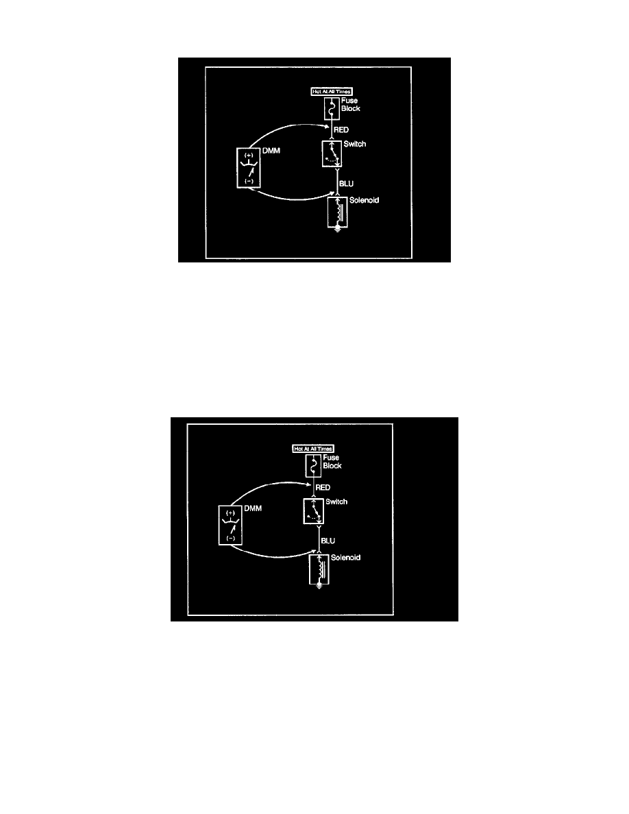
This test checks for voltage being lost along a wire or through a connection or switch.
1. Connect the positive lead of a DMM to the end of the wire or to one side of the connection, or to the switch whichever is closer to the battery.
2. Connect the negative lead to the other end of the wire or to the other side of the connection, or switch.
3. Operate the circuit.
4. The DMM will show the difference in voltage between the two points.
Testing For Voltage
NOTE: Do not insert a DMM test probe into any connector or fuse block terminal. The diameter of the DMM test probe will deform most terminals. A
deformed terminal can cause a poor connection between the device, which can result in system failures. Always use the J 35616-A Connect Test Adapter
Kit when using a DMM in order to probe terminals.
This test checks for voltage along a wire through a connection or switch.
1. Apply power to the circuit.
2. Place meter leads in the COM (black) and The DTC ohm inputs.
3. Place the rotary switch (meter) in the The DTC (AC) or The DTC (DC) position.
4. Connect the positive lead of a DMM to the end of the wire, (or to one side of the connection or switch) which is closer to the battery.
5. Connect the negative lead to the other end of the wire (or the other side of the connection or switch).
6. Operate the circuit.
Testing For Continuity
With a DMM
Continuity tests work well for detecting intermittent shorts to ground and can be performed by setting the
DMM to ohms, then pressing the PEAK MIN MAX button. An audible tone is heard whenever the DMM detects continuity for at least 1 millisecond.
This test checks for continuity along a wire, through a connection or switch.