
Hombre S Regular Cab 4WD V6-4.3L (1999)
Circuit Description
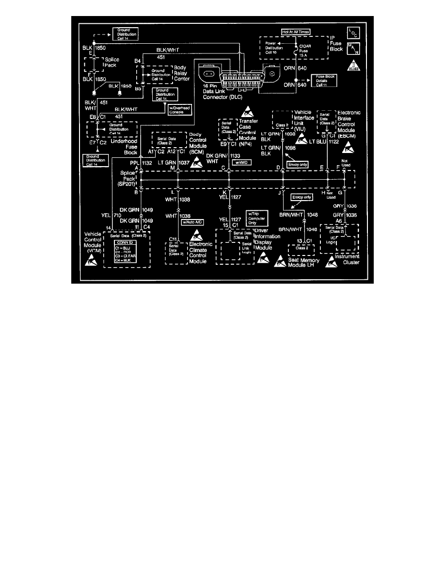
The Class 2 Serial Data circuit to the DLC allows bi-directional communication between the VCM and the scan tool. This is accomplished through pin 2
of the DLC. If communication between the scan tool and the VCM cannot be established, use the procedure in the DLC Diagnosis table in order to
diagnose the condition.
Diagnostic Aids
Check for the following items:
-
For the VCM to establish communication with the scan tool, the system voltage must be between 9 - 16 volts If the system voltage is not within
this range, refer to Charging System Check.
-
Select the correct application (model year, truckline, VIN code) on the scan tool. An intermittent may be caused by any of the following
conditions:
-
A poor connection
-
Rubbed through wire insulation
-
A broken wire inside the insulation
Thoroughly check any circuitry that is suspected of causing the intermittent complaint. Refer to Intermittents and Poor Connections Diagnosis.
If a repair is necessary, then refer to Wiring Repairs or Connector Repairs.