
Hombre S Regular Cab 4WD V6-4.3L (1999)
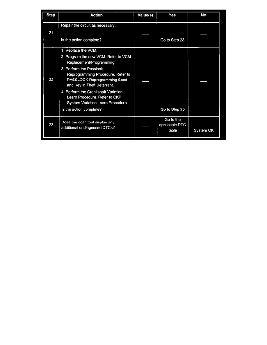
Steps 21 - 23
Test Description
2. This step determines if the scan tool is operating correctly.
6. This step monitors the actively communicating modules with the scan tool's Diagnostic Circuit Check function. An active module is a module that
is successfully communicating on the Class 2 Serial Data line with the scan tool. An inactive module is a module which had previously established
communication with the scan tool, but currently is not communicating. If a module is not listed at all, then the module never successfully
established communications with the scan tool. Refer to Data Link Communications Diagnostic System Check in Data Link Communications.
7. This step isolates The VCM by disconnecting all the other components on the Class 2 Serial Data Circuit. If VCM Class 2 Serial Data exists after
disconnecting all other components on the Class 2 Serial Data Circuit, refer to Data Link Communications Diagnostic System Check in Data Link
Communications.
12. This step determines if voltage is not available at the DLC due to an open battery feed fuse. If the fuse is open, determine if the open was due to a
short in the battery feed circuit before replacing the fuse.