
Hombre S Regular Cab 4WD V6-4.3L (1999)
Body Control Module: Service and Repair
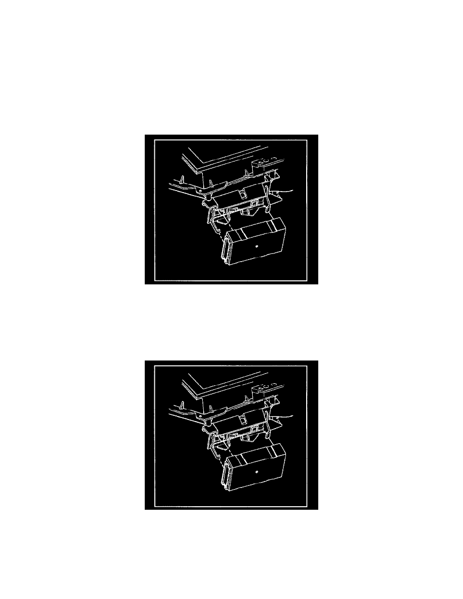
Removal and Installation
Removal Procedure
Replacing the Body control module (BCM) may be necessary when you service the Body control system.
IMPORTANT: The ignition switch should be in the OFF position when connecting or disconnecting the connectors to the BCM. Always disconnect
the Brown BCM connector FIRST and connect the Brown BCM connector LAST. The BCM can set DTC(s) with the ignition switch in the OFF
position. The BCM has battery run down protection for the courtesy lamp circuit. The BCM battery run down protection can not detect shorts on inputs
or other circuits which it does not control The scan tool can be used to put the BCM to sleep in order to check for current draws on circuits which are not
controlled by the BCM or controlled by the battery run down protection system. If an excessive current draw is detected, refer to Battery (Parasitic) Load
Test.
1. Remove the left instrument panel sound insulator from the vehicle.
2. Remove the center instrument panel sound insulator from the vehicle.
3. Disconnect the electrical connectors from the Body control module.
4. Bend the 2 snap retainers back slightly and pull the left side of the Body control module forward.
5. Remove the Body control module from the bracket at an angle.
Installation Procedure
1. Install the Body control module to the bracket at an angle under the wide hook retainer, with the label facing away from the bracket.
2. Install the module connector end. Position the module above and between the 2 snap retainers.
3. Slide the Body control module under the wide hook retainer.
4. Apply pressure on the left side of the Body control module in order to move the module toward the mounting bracket base. Snap the module into
place.
5. Ensure that the module is fully seated. Ensure that both snap retainers are holding the module.
6. Connect the electrical connectors to the Body control module.