
Hombre S Regular Cab 4WD V6-4.3L (1999)
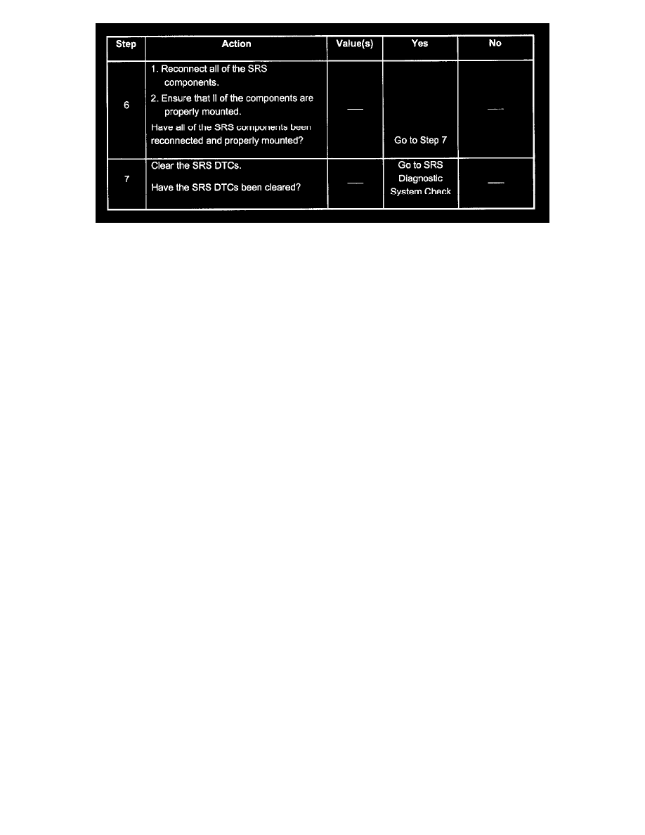
Steps 6 - 7
Test Description
The numbers below refer to the step numbers on the diagnostic table:
2. This test confirms a circuit malfunction. If no current malfunction is occurring (history DTC set), refer to the Diagnostic Aids for the appropriate
DTC table as indicated through the scan tool. Do not replace the supplemental restraint sensing and diagnostic module (SDM) for a history DTC
other than DTC B1071.
3. This test inspects for a malfunction introduced into the SRS during the diagnostic process. A malfunctioning SDM is unlikely to cause a new
malfunction to occur during this process.
4. When you have found all circuitry outside the SDM to operate properly, as indicated by the appropriate diagnostic table, replace the SDM.
This table assumes that the SRS Diagnostic System Check and either a symptom table or a diagnostic trouble code table diagnosis has been
performed.When all circuitry outside the supplemental restraint sensing and diagnostic module (SDM) has been found to operate properly, as indicated
by the appropriate diagnostic table, and the symptom or DTC remains current, the following diagnostic procedures must be performed to verify the need
for SDM replacement