
Hombre S Regular Cab 4WD V6-4.3L (1999)
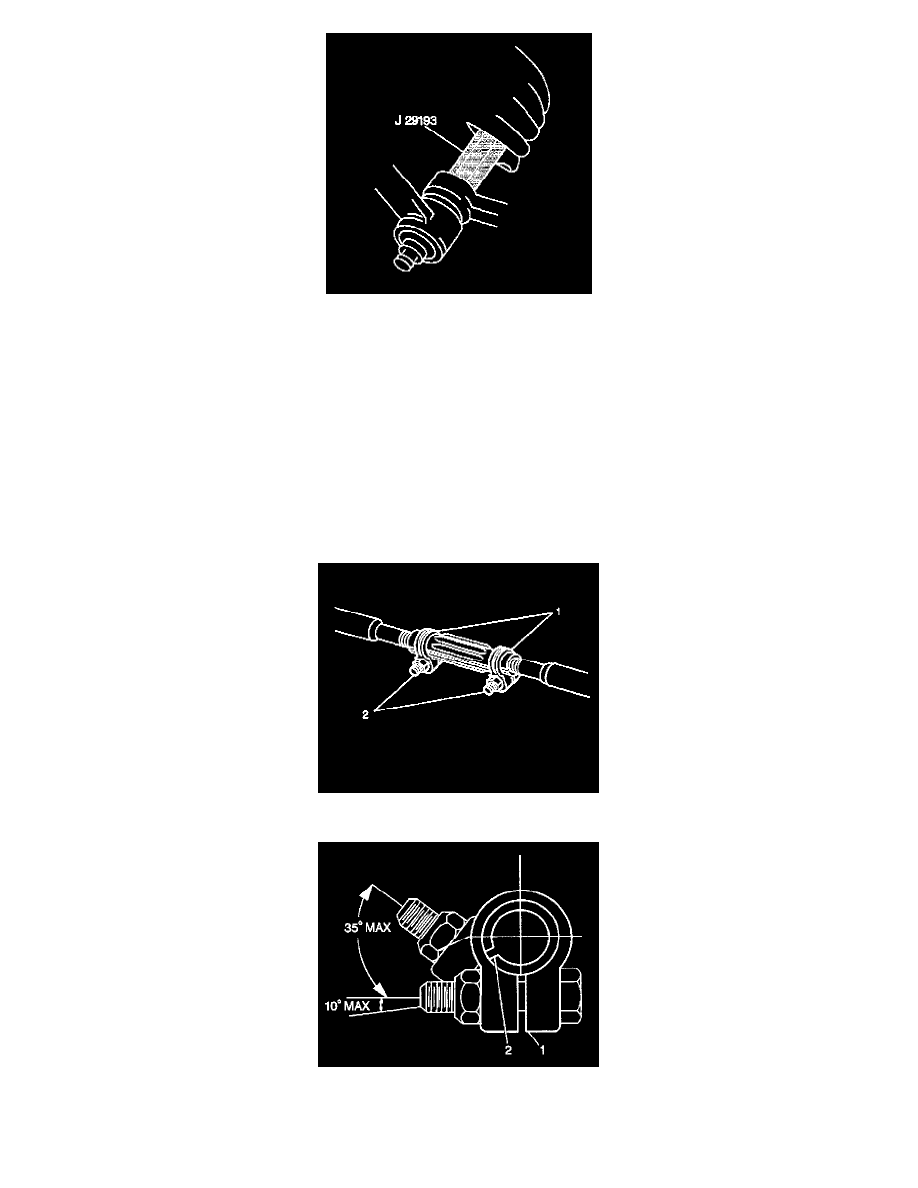
7. Seat the taper using J 29193 or J 29194.
Tighten
Tighten J 29193 or J 29194 to 54 N.m(40 lb ft).
8. Remove J 29193or J 29194 from the outer tie rod ball stud.
9. Install the nut to the outer tie rod ball stud.
Tighten
Tighten the outer tie rod ball stud nut to 53 N.m (39 lb ft).
Important: Do not back the nut off in order to align the cotter pin hole. Advance the nut in order to align the nut slot with the cotter pin hole.
10. Install the new cotter pin to outer tie rod nut.
11. Spread the cotter pin ends
12. Lower the vehicle.
13. Adjust the front toe.
14. Position the two clamps (2) between the locating dimples (1) at either and of the adjuster tube.
15. The clamps must be positioned within the correct angular travel, as shown.
16. Ensure that the clamp slot (2) is not aligned with the adjuster tube slot (1).
17. Maintain the position of each tie rod end as the clamps are tightened in order to ensure free movement of each joint.