
Hombre XS Space Cab L4-2.2L CPC (1997)
Remove
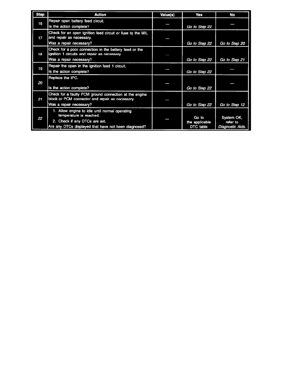
Number(s) below refer to step number(s) on the Diagnostic Table.
1. The Powertrain OBD System Check prompts the technician to complete some basic checks and store the freeze frame and failure records data on
the scan tool, if applicable. This creates an electronic copy of the data taken when the malfunction occurred. The information is stored in the scan
tool for later reference.
3. Connections that are suspected of being faulty should be thoroughly checked as described in the diagnostic aids.
4. If the engine fails to start and the MIL is inoperative, then the fault can be isolated to either the PCM ignition feed 1, the battery feed, a poor
ground at the engine block, or the PCM.
6. Probing the MIL circuit with a test light to ground simulates the PCMs control of the MIL. If the MIL illuminates, then the malfunction can be
isolated to the control of the MIL or a poor connection at the MIL terminal to the PCM. Connections that are suspected of being faulty should be
thoroughly checked as described in the diagnostic aids.
8. It takes very little resistance for the battery and ignition 1 feed circuits to cause an intermittent condition and should also be checked for a poor
connection as described in diagnostics aids.
11. Before replacing the PCM, check for backed out terminals, improper mating, broken locks, improperly formed or damaged terminals, poor
terminals to wiring connections or physical damaged to the wiring harness.
Replacement PCMs must be reprogrammed and the crankshaft position system variation procedure must be performed. Refer to the latest Isuzu
Technical Communication System (ITCS) information for programming procedures and also refer to the CKP System Variation Learn Procedure.
13. A shorted MIL circuit can be diagnosed with a scan tool. Refer to PCM Outputs Diagnosis.
14. An open MIL circuit can be diagnosed with a scan tool. Refer to PCM Outputs Diagnosis.
16. For MIL bulb replacement procedures, refer to Instrument Panel and Console of the service manual.
17. For IPC replacement procedures, refer to Instrument Panel and Console of the service manual.
20. PCM grounds will only cause a problem if all of the grounds are not making a good connection.
If a PCM ground problem is suspected, the most probable place to check is where all the grounds meet, at the engine block.
21. PCM grounds will only cause a problem if all of the grounds are not making a good connection.
If the PCM ground problem is suspected, the most probable place to check is where all of the grounds meet, at the engine block. Connections that
are suspected of being faulty should be thoroughly checked as described in the diagnostic aids.
22. If no faults have been found at this point and no DTCs were set, refer to the diagnostic aids for additional checks and information.