
Hombre XS Space Cab L4-2.2L CPC (1997)
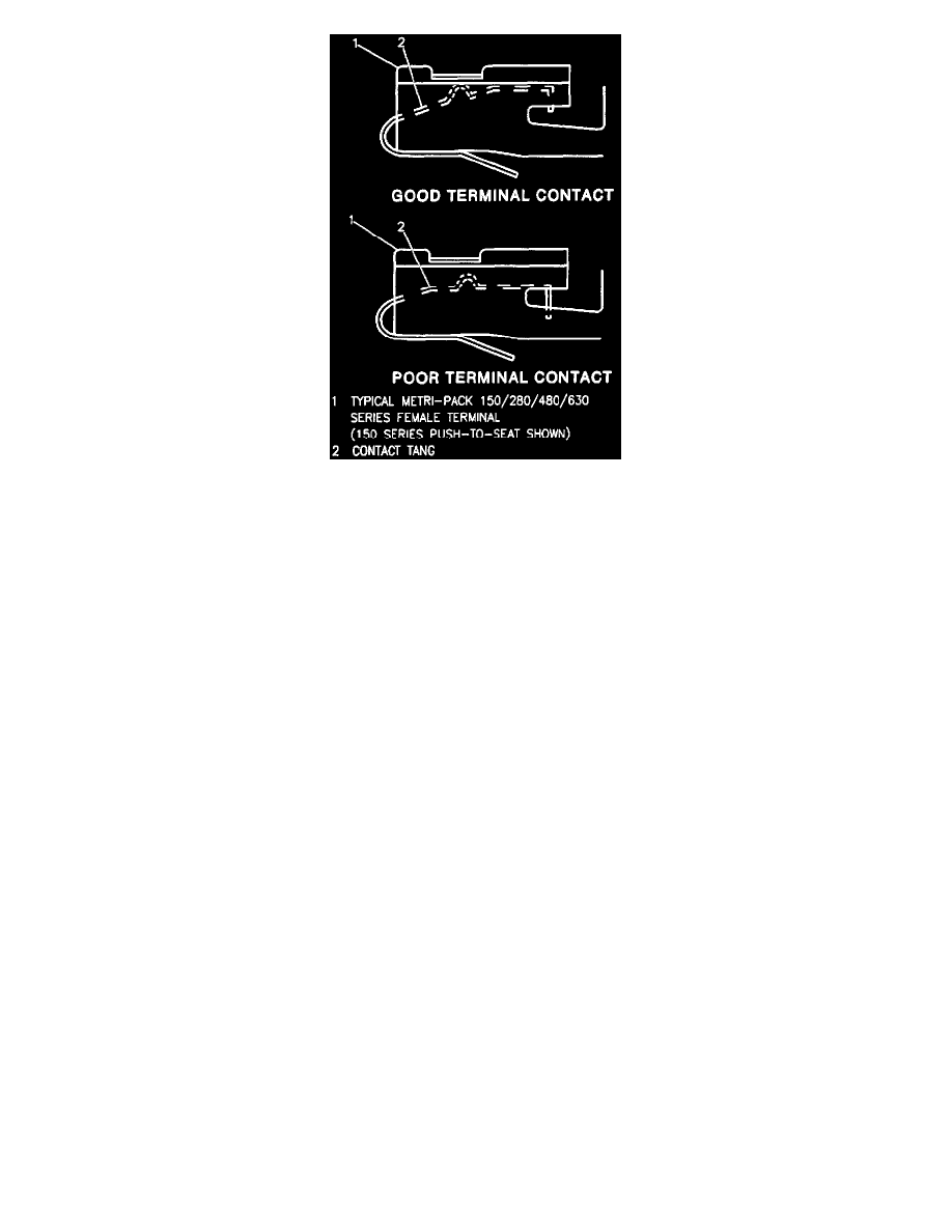
Deformation is caused by probing the mating side of a connector terminal without the proper adapter, improperly joining the connector halves or
repeatedly separating and joining the connector halves. Deformation, usually to the female terminal contact tang, can result in poor terminal contact,
causing an open or intermittently open circuit.
Follow the procedure below to check terminal contact.
1. Separate the connector halves.
2. Inspect the connector halves for contamination. Contamination will result in a white or green build-up within the connector body or between
terminals, causing high terminal resistance, intermittent contact, or an open circuit. An underhood or underbody connector that shows signs of
contamination should be replaced in its entirety: terminals, seals, and connector body.
3. Using an equivalent male terminal from the J 38125-A Terminal Repair Kit, check the retention force of the female terminal in question by
inserting and removing the male terminal to the female terminal in the connector body. Good terminal contact will require a certain amount of
force to separate the terminals.
4. Using an equivalent female terminal from the J 38125-A Terminal Repair Kit, compare the retention force of this terminal to the female terminal in
question by joining and separating the male terminal to the good female terminal, and then joining and separating the male terminal to the female
terminal in question. If the retention force is significantly different between the two female terminals, replace the female terminal in question.
If a visual (physical) check does not reveal the cause of the problem, the vehicle may be able to be driven with a DMM connected to the suspected circuit
An abnormal voltage reading when the problem occurs indicates the problem may be in that circuit.
Detecting Electrical Intermittents
Use the following procedure to detect intermittent terminal contact or a broken wire with an intermittent connection inside the insulation.
The J 39200 Digital Multimeter (DMM) has the ability to monitor current, resistance, or voltage while recording the minimum (MIN) and maximum
(MAX) values measured. The DMM can also be set to display the average (AVG) value measured.
When diagnosing circuits that have voltage applied, use the voltage setting to monitor a connector (or length of a circuit) which is suspected of having an
intermittent connection but is currently operating normally.
1. Connect the J 39200 Digital Multimeter to both sides of a suspect connector (still connected) or from one end of a suspect circuit to the other. This
will continuously monitor the terminal contacts or length of wire being checked. Refer to "Digital Multimeter (DMM) Connections" in this section
for examples of the various methods for connecting the DMM to the circuit
2. Set the DMM for voltage. Since the "MIN MAX" mode does not use auto ranging, manually select the voltage range necessary before proceeding.
3. Press the "MIN MAX" button. The DMM should read "100 ms RECORD" (100 millisecond record) and emit a 1/4 second beep. The DMM is
now ready to record and will generate an audible tone for any change in voltage. At this point, you may wish to press the "PEAK MIN MAX"
button, which will record any voltage variations that occur for at least 1 millisecond.
4. Try to simulate the condition that is potentially causing an intermittent connection, either by wiggling connections or wiring, test driving or
performing other operations. If an open or resistance is created, a voltage will be present and the DMM will emit a tone for as long as the open or
resistance exists. Any change in voltage will cause the DMM to emit a tone for no less than 1/4 second. (Listening for a tone while manipulating
wiring is very helpful for narrowing down an intermittent connection.)
Use the MIN and MAX values when the DMM is out of sight or sound range, in noisy areas or for test driving when it may not be possible to
monitor the DMM.
To check the MIN and MAX recorded voltages press "MIN MAX" once for MAX and twice for MIN. A variation between MIN and MAX
recorded voltages (unless nearly 0 volts) suggests an intermittent open or that resistance exists and should be repaired as necessary.