
Hombre XS Space Cab L4-2.2L CPC (1997)
Malfunction Indicator Lamp: Testing and Inspection
Data Link Connector Diagnosis
Data Link Connector Diagnosis
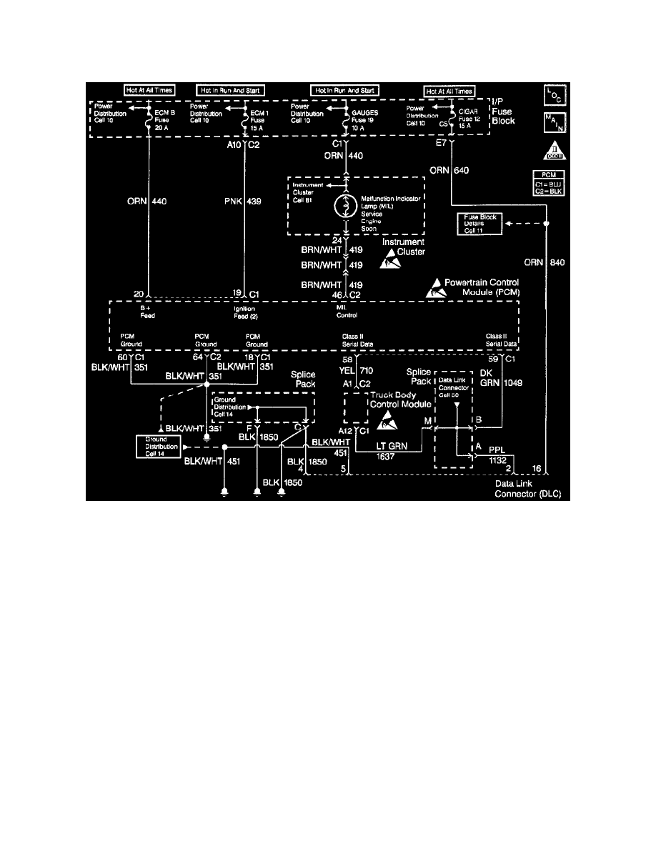
Circuit Description
The provision for communicating with the control module is the Data Link Connector (DLC). It is usually located under the instrument panel. The
DLC is used to connect to a scan tool. Some common uses of the scan tool are listed below:
-
Identifying stored Diagnostic Trouble Codes (DTCs).
-
Clearing DTCs.
-
Performing output control tests.
-
Reading serial data.
Battery power and ground is supplied for the scan tool through the DLC. The Class 2 serial data circuit to the DLC allows the PCM to
communicate with the scan tool. The Class 2 serial data circuit is also used to communicate with the Electronic Brake Control Module
(EBCM), and the Truck Body Control Module.
Diagnostic Aids
Some scan tools may require an external power supply. Make sure your scan tool is using the correct power feed.
Ensure that the correct application (model year, carline, VIN code) has been selected on the scan tool. If communication still cannot be
established, try the scan tool on another vehicle to ensure that the scan tool, or cables are not the cause of the condition.
An intermittent may be caused by a poor connection, rubbed through wire insulation or a wire broken inside the insulation.
Any circuitry, that is suspected as causing an intermittent complaint, should be thoroughly checked for the following conditions:
-
Backed out terminals. Improper mating of terminals.
-
Broken locks.
-
Improperly formed or damaged terminals.
-
Poor terminals to wiring connection.
-
Physical damaged to the wiring harness.
-
Corrosion.
Test Description