
Hombre XS Space Cab L4-2.2L CPC (1997)
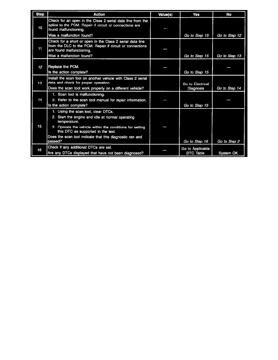
Number(s) below refer to the step number(s) on the Diagnostic Table.
1. The Powertrain OBD System Check prompts the technician to complete some basic checks and store the Freeze Frame Data and the Failure
records on the scan tool if applicable. This creates an electronic copy of the data taken when the malfunction occurred. This information on the
scan tool can be referred to later.
2. If the scan tool requires an external power supply, check the external supply for proper voltage and ground as well as the voltage and ground
supplies in the DLC.
7. Locate and repair any shorts that may have caused the fuse to open before replacement, if the no voltage conditions due to an open fuse.
12. Replacement PCMs must be reprogrammed and the crankshaft position system variation procedure must be performed. Refer to the latest Isuzu
Technical Communication System (ITCS) information for programming procedures and also refer to the CKP System Variation Learn Procedure.
14. The scan tool, or associated cables could be faulty. Refer to the scan tools manual for repair information.