
Hombre XS Space Cab L4-2.2L CPC (1997)
Number(s) below refer to the step number(s) on the Diagnostic Tables.
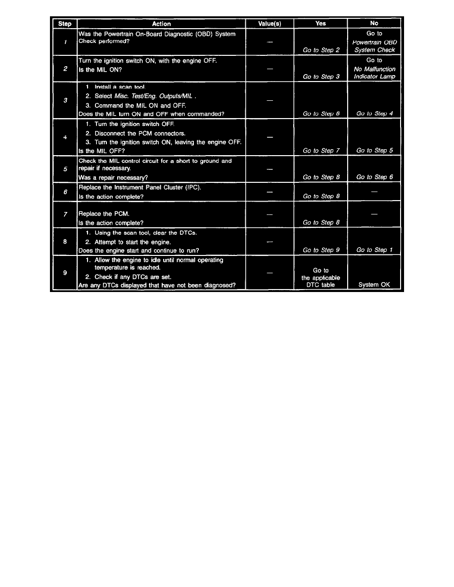
1. The Powertrain OBD System Check prompts the technician to complete some basic checks and store the freeze frame and failure records data on
the scan tool if applicable. This creates an electronic copy of the data taken when the malfunction occurred. The information is then stored in the
scan tool for later reference.
2. When the ignition is turned ON, the MIL should momentarily flash ON and OFF then remain ON until the engine is running or if an emission
related DTC is stored.
3. This step checks the ability of the PCM to control the MIL. The scan tool has the ability to command the MIL ON and OFF.
5. A shorted MIL circuit can be diagnosed with a scan tool. Refer to PCM Outputs Diagnosis.
6. For Instrument Panel Cluster (IPC) replacement procedures, refer to Instrument Panel of the service manual.
7. Replacement PCMs must be reprogrammed and the crankshaft position system variation procedure must be performed. Refer to the latest Isuzu
Technical Communication System (ITCS) information for programming procedures and also refer to the CKP System Variation Learn Procedure.