
Hombre XS Space Cab L4-2.2L CPC (1997)
Manifold Absolute Pressure Sensor: Diagram Information and Instructions
Abbreviations
A/C ............................................................................................................................................................................................................... Air Conditioning
CKT ............................................................................................................................................................................................................................. Circuit
CONN ..................................................................................................................................................................................................................... Connector
EBCM ................................................................................................................................................................................ Electronic Brake Control Module
EBTCM ........................................................................................................................................................ Electronic Brake and Traction Control Module
ECM .................................................................................................................................................................................................. Engine Control Module
HARN ......................................................................................................................................................................................................................... Harness
I/P ................................................................................................................................................................................................................. Instrument Panel
IPC ................................................................................................................................................................................................... Instrument Panel Cluster
LH ........................................................................................................................................................................................................................... Left Hand
PCM ............................................................................................................................................................................................ Powertrain Control Module
RH ......................................................................................................................................................................................................................... Right Hand
TERM ........................................................................................................................................................................................................................Terminal
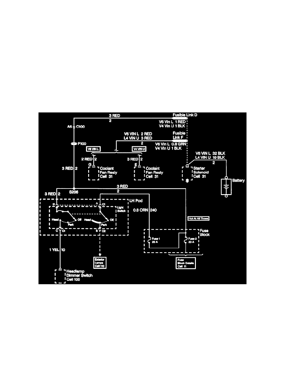
Power Distribution
The Power Distribution schematic shows the wiring from the Battery and Generator to the Starter Solenoid, Fuse Block, ignition Switch and Light
Switch. The first component after a Fusible Link is also shown. In certain instances, the first component after a Fuse Block fuse and Light Switch is also
shown.
The Power Distribution schematic refers to Fuse Block Details or the appropriate section schematics. By using these schematics, power distribution
wiring can be followed from the Battery and Generator to the first component after a Fusible Link, Fuse or Light Switch. The ability to follow the power
distribution wiring to the first component in each circuit is extremely helpful in locating short circuits which cause fusible links and fuses to open.
A sample Power Distribution schematic. it shows how voltage is applied from the positive battery terminal to the various circuits on the vehicle. For
example, battery voltage is applied to the Starter Solenoid, Fusible Link D, Fuses 1 and 2 in the Fuse Block and the Light Switch in the LH Pod. These
fuses are said to be "Hot At All Times", since battery voltage is always applied to them.
Notice that battery voltage is also applied to "Fusible Link F" and "Coolant Fan Relay."